9
EXISTING CONSTRUCTION INSTALLATION INSTRUCTIONS (Continued)
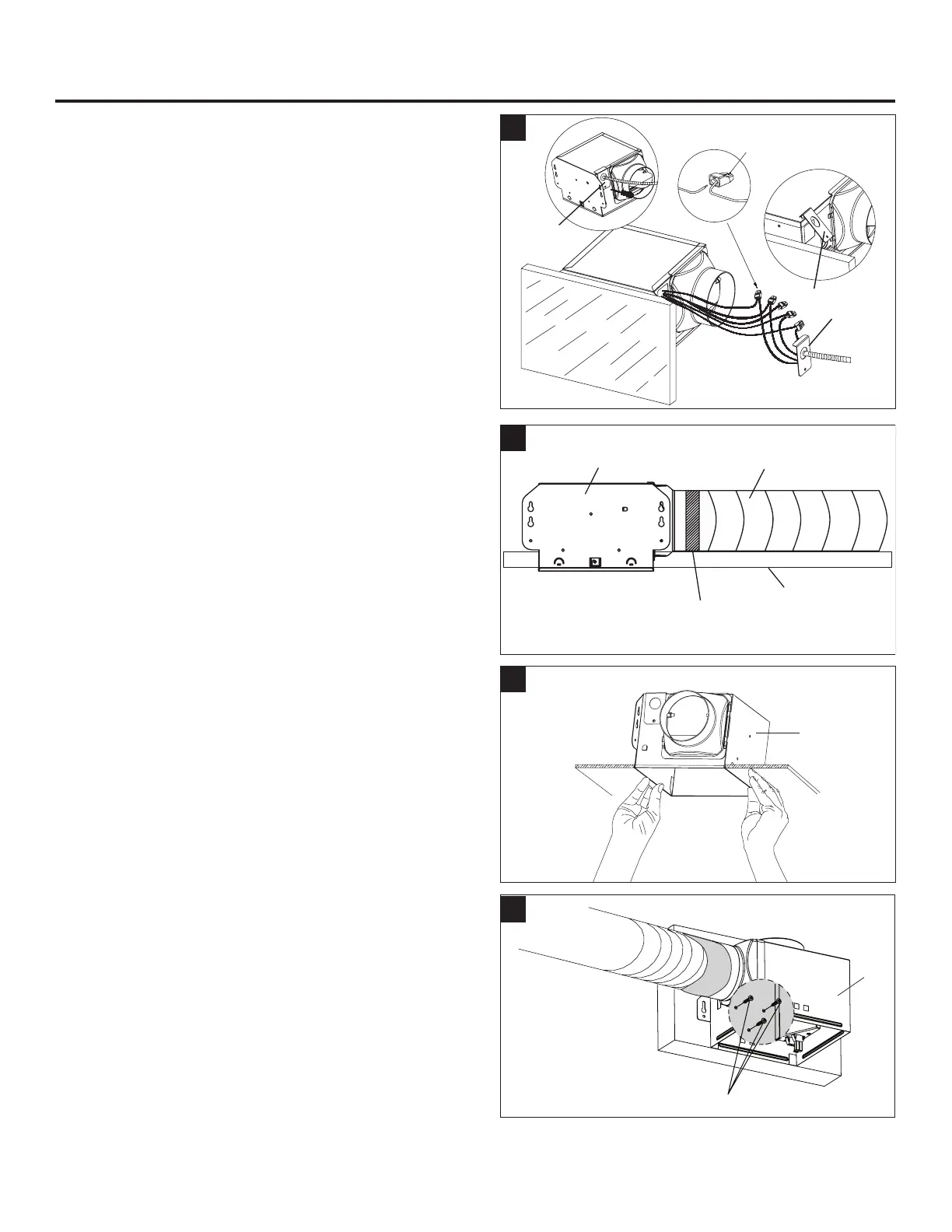
7. Pull the house wires through the hole in the wiring box cover.
Using the quick connectors, connect the house wiring from
the wall switch to the fan housing (A). 14 AWG is the smallest
conductor that should be used for branch-circuit wiring. Please
refer to the wiring diagrams on page 4 to ensure proper wire
connections are made.
Carefully push the wire connections into the wiring box housing
and reattach the wiring box cover.
CAUTION: If your electrical wires do not match the colors
listed, consult a licensed electrician to determine what each
house wire represents before connecting the fan.
Quick
connector
Wiring
box cover
Wiring box
cover
7
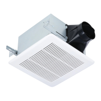
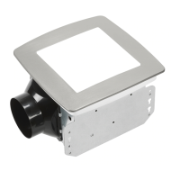
8. Connect a 4 in. circular duct to the duct connector on the fan
housing (A), securing it with duct tape or a clamp. Vent the
duct to the outside.
4 in.duct
A
Ceiling
Duct tape
or clamp
8
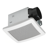
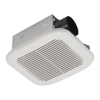
9. With the wiring and duct connected, insert the fan housing (A)
into the ceiling hole. Position the fan housing (A) so the
bottom edge of the fan housing (A) is ush with the ceiling
board.
A
9
10. Mount the fan housing (A) to the joist with three wood screws
(AA) through the holes in the side of the fan housing (A).
The fan housing (A) must be installed ush with the ceiling
board or the grille mounting springs will not be long enough to
insert into the slots inside the fan housing (A).
10
A
AA