9
Lowes.com
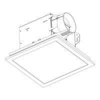
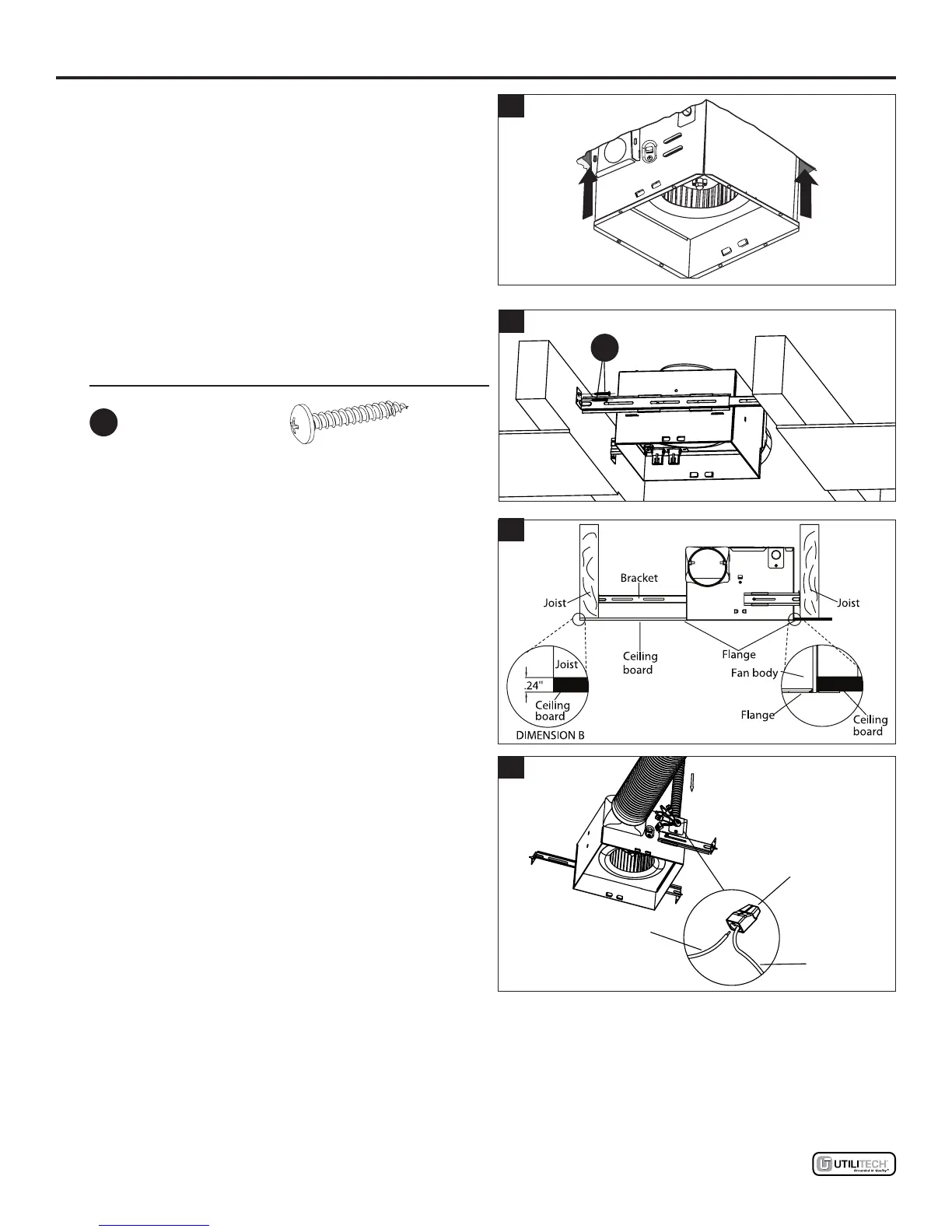
EXISTING CONSTRUCTION ASSEMBLY INSTRUCTIONS
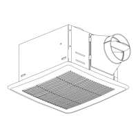
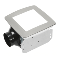
5. Insert fan body (A) into the ceiling cut out making
sure to align the duct connector with the fan body
(A). Flange should be on the bathroom side of
the drywall.
NOTE: Duct/outlet adapter can be removed for
easier installation through the ceiling opening.
6. Mount the fan body to joist using the suspension
brackets and long wood screws.
Hardware Used
AA
Long wood screw x 2
7. CAUTION: Dimension “B” should allow for thick-
ness of ceiling board used in your applicaton.
Do not ush mount to joist. Flange should
be ush with ceiling board.
8. Refer to wiring diagram on page 5. Remove the
junction box cover. Using quick connectors,
connect house wires to ventilating fan wires:
black to black; white to white; green to green.
Replace the junction box cover.
CAUTION: If your house wires do not match
these colors, you must determine what each
house wire represents before connecting and
you may need to consult an electrical contractor
to determine this safely. Mount junction box
cover carefully so lead wires are not pinched.
7
Wiring
box
Quick
connector
Product
wires
House
wires
8
AA
6
5