Lowes.com Lowes.com
8
9
ASSEMBLY INSTRUCTIONS
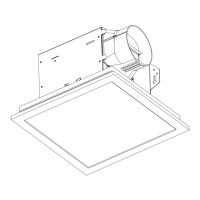
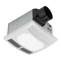
b. Install the grille (A) into the fan body (C) using
the medium machine screw (BB).
3b
3. Completing the installation
a. Insert the plug from the heating unit into the
receptacle marked “Heat”, the plug from the
fan into the receptacle marked “Vent”, and
the plug from the light into the receptacle
marked “Light”.
3a
Vent
Light
Heat
WIRING INSTRUCTIONS
1. Follow all local electrical and safety codes.
2. Never place a switch where it can be
reached from a tub or shower.
3. Using wire nuts (not included), connect house power
wires to fan wires.
4. 14 AWG (2.1 mm
2
) is the smallest conductor that
shall be used for branch-circuit wiring. Each power
wire (light, fan, heater) must have its own switch
to operate independently.
5. For supply connections, use wire rated for at least 90º
C. See wiring diagram for wire size.
• Make sure power is switched off at service panel before starting installation.
• All electrical connections must be made in accordance with local codes, ordinances, or national
electrical code. If you are unfamiliar with methods of installing electrical wiring, secure the services
of a qualied electrician.
• This unit must be wired on a separate 20 amp circuit.
• If your house wires do not match these colors, you must determine what each house wire
represents before connecting and you may need to consult an electrical contractor to determine
this safely.
WARNING:
1
POWER
HOUSE ELECTRICAL BOX HOUSE ELECTRICAL BOX
NEUTRAL
GROUND
CAUTION: Do not use long wood screw
(CC) in place of medium machine screw (BB).
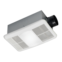
CAUTION: Install a 60 watt maximum light
bulb (not included).
CAUTION
OPERATING INSTRUCTIONS
CAUTION: Failure to secure the reector screws may result in a rattling or humming noise.
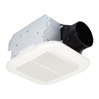
This unit must be properly installed before it is used. Follow instructions for cleaning,
user-maintenance and operations recommended by the manufacturer, such as lubrication or non
lubrication. Any other servicing should be performed by an authorized service representative.
1. Turn on the light switch to turn on the light bulb.
2. Turn on the vent switch to operate the fan mode.
3. Turn on the heat switch to operate the heater mode.
WARNING:
c. Install the light lens (B) into grille (A).
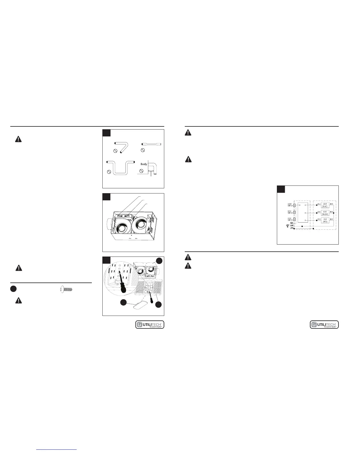
WIRING DIAGRAM
CAUTION: All ducting must comply with local
and national building codes.
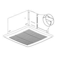
a. Snap the damper/duct connector (not included)
onto the fan body. Make sure that tabs on the
connector lock into housing slots.
b. Insert the duct into the duct connector and
tape all duct work connections to make them
secure and air tight.
c. Do not install the unit where ducts are
congured as shown in Figure 2.
d. Install the duct with a gradient 1°~2° to the
outside.
2. Connecting the duct
2
BB
A
C
B
Hardware Used
x 1
Medium Machine Screw
AWG18AWG18
AWG18AWG18
AWG14AWG14
Turning angle too large
Duct shrink
Elbow near the body
Too many elbows
Minimum 18 in.
HOUSE ELECTRICAL BOX HEATER VENTILATION FAN