EasyManua.ls Logo

Utility Solutions LOAD-RANGER XLT Series - User Manual

Utility Solutions LOAD-RANGER XLT Series
16 pages
Print Icon
To Next Page IconTo Next Page
Loading...
Phone (828)323-8914
Fax (828)323-8410
Email sales@utilitysolutionsinc.com
Web www.utilitysolutionsinc.com
101 33
rd
Street Drive SE · Hickory, NC 28602
Maintenance Manual
Contents
Overview 3
Tools, Parts, and Supplies 3
Components and Assemblies 4
Disassembly Procedure 7
Probe Shaft Inspection and Cleaning 9
Yellow Tube & Components Inspection and Cleaning 10
Overhead Arm Assembly Inspection and Cleaning 11
Black Tube Assembly & Conductor Path Inspection and Cleaning 12
Reassembly Procedure 13
LOAD-RANGER
®
XLT Load Break Tool
USLR-XLT-1 Up To 27 kV Load Break Tool
USLR-XLT-2 27 kV - 38 kV Load Break Tool
B-01286 USLR-XLT Maintenance
Manual (11-25-19)
Question and Answer IconNeed help?

Do you have a question about the Utility Solutions LOAD-RANGER XLT Series and is the answer not in the manual?

Summary

Overview

Tools, Parts, and Supplies

Components and Assemblies

Disassembly Procedure

Probe Shaft Inspection and Cleaning

Inspect and clean the probe shaft assembly for damage, wear, and proper function of components.

Yellow Tube & Components Inspection and Cleaning

Inspect and clean the yellow tube assembly, female contact, and trigger mechanism for wear and damage.

Overhead Arm Assembly Inspection and Cleaning

Inspect the overhead arm assembly for damage, proper movement, and smooth pivoting of its components.

Black Tube Assembly & Conductor Path Inspection and Cleaning

Inspect the black tube assembly and conductor paths for damage, gouging, or tracking.
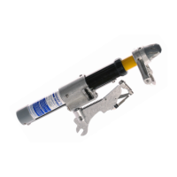
Reassembly Procedure

Utility Solutions LOAD-RANGER XLT Series Specifications

General IconGeneral
BrandUtility Solutions
ModelLOAD-RANGER XLT Series
CategoryTools
LanguageEnglish