2 EASY
DT-BDU BUS AMPLIFIER
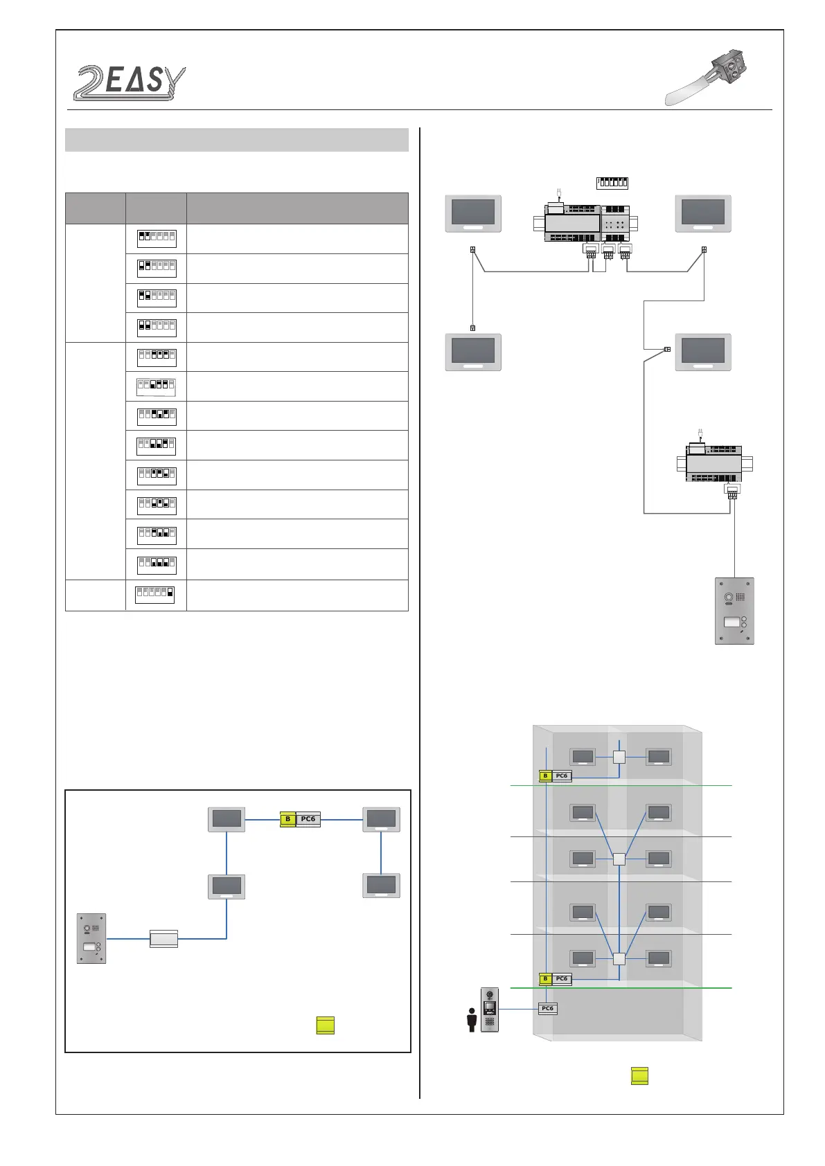
The detail settings of DIP are as follows:
Work Mode:
Repeater Mode:
DT-BDU can extend the distance of DT system
when works in repeater mode. As follows:
Max 140m from the rst door station to DT-BDU
Max 140m from the last indoor monitor to DT-BDU
Router Mode:
Use 8 DT-BDUs at most in this mode.
1 2 3 4 5 6
ON
Bit
Bit-1~Bit-2
Set to the Repeater mode.
Bit-6
Bit State Description
Set to the first DT-BDU.
1 2 3 4 5 6
ON
1 2 3 4 5 6
ON
1 2 3 4 5 6
ON
Set to the Router mode.
Set to the Gateway mode.
Reserved.
Bit-3~Bit-5
1 2 3 4 5 6
ON
Set to the third DT-BDU.
Set to the second DT-BDU.
1 2 3 4 5 6
ON
1 2 3 4 5 6
ON
Set to the fourth DT-BDU.
1 2 3 4 5 6
ON
Set to the fifth DT-BDU.
1 2 3 4 5 6
ON
Set to the sixth DT-BDU.
1 2 3 4 5 6
ON
Set to the seventh DT-BDU.
1 2 3 4 5 6
ON
Set to the eighth DT-BDU.
1 2 3 4 5 6
ON
Used to video Impendence match, set to ON.
1 2 3 4 5 6
ON
Repeater Mode
PC6
B
DT-BDU
Wiring diagram:
BUS(IM) BUS(DS)
PC6
AC~
BUS(IM) BUS(DS)
PC6
AC~
OUT DS
BDU
IN IN
1 2 3 4 5 6
ON
B
DT-BDU
4A
4A
PC6
1 2 3
654
7 8 9
#0
*
4A
DT System Test Manual-12-
 Loading...