ENGLISH
9
PREPARATORY STEPS
CAREFULL
Y OBSERVE EUROPEAN REGULATIONS EN12445 AND
EN12453 (WHICH REPLACE UNI 8612).
Always check the following:
• Your gate should have a strong and suitable build; no
wickets should be present on the sliding gate.
• The sliding gate should not tilt excessively during its entire
run.
• The gate should be able to slide freely on its guiding
surface without an excessive friction.
• Install both closing and opening limit switches, in order to
prevent the gate going off the guiding surface.
• Remove any manual locks.
•
Bring power cable ducts near the bottom of the gate
(diameter 20 / 30 mm) and of the external devices
(photocells,
flasher, key selector).
INSTALLATION
• Prepare a cement base raised 40 - 50 mm from the ground
on which the metal plate will be fixed.
• Provide a channel for two hoses that will house the cables
in the main hole (A) on the counter-plate.
• Such counter-plate shall be fixed to the ground by means of
four anchors next to the already-made holes (B).
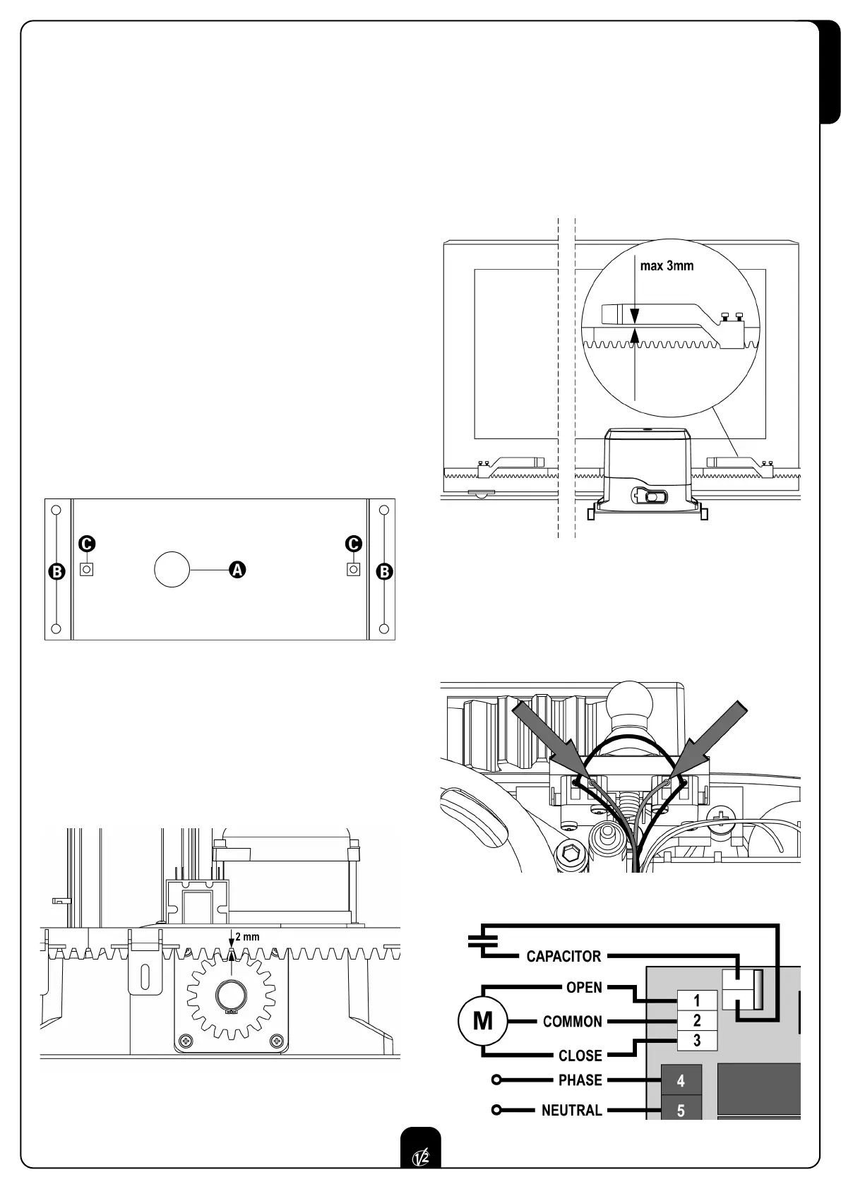
• Fix the motor on the counter-plate by means of the
bolts (3) and the nuts fitted in the holes (C).
MOUNTING THE RACK
Release the motor and tur
n the gate completely open.
F
ix all the rack elements to the gate, making sure that they
stand at the same height than the motor pinion.
It is impor
tant that the rack be positioned 1 or 2 mm abo
ve
the motor pinion,
in order to pre
vent that the motor be
damaged under the w
eight of the gate.
INSTALLING THE LIMIT SWITCHES
Install limit switches on the rack and fix them using the screws
pro
vided in the tool kit.
m ATTENTION: check that the limit switch bracket will work
effectively on the limit switch spring of the motor.
If necessar
y add thickness between the lower part of the rack
and the limit switch bracket in order to keep to the
measurement as stated in the figure 1.
The limit switches are wired for installation with the motor on
the right of the gate opening.
If the motor is installed on the left of the gate opening, it will
be necessary to invert the blue and brown cables on the limit
switch (fig. 2) and also the motor connector (1-2-3) on the
control unit (fig. 3).
Fig. 2
Fig. 1
Fig. 3
 Loading...