ENGLISH
11
CONTROL UNIT
•
230/120 VAC power supply for 1 single-phase motor with
limit switches (700W max).
•
Input for key switch or push-button.
• Input for safety photocell.
•
Built-in self-learning receiver (433 MHz).
• Operation logic programming through dip-switch.
• Motor power and working times adjustment by means of
potentiometers.
•
Input monitored through LED (START, STOP, PHOTOCELL,
OPENING and CLOSING LIMIT SWITCH)
• The control unit, which is compatible with the Personal Pass
system, enables you to store up to 83 different codes.
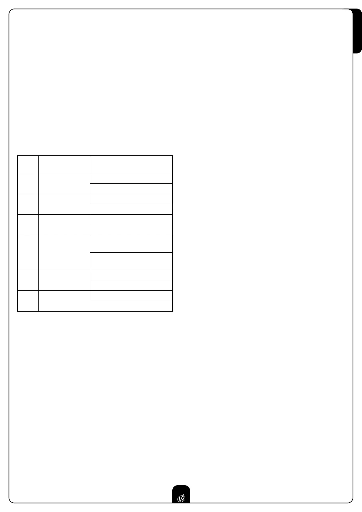
PROGRAMMING THE OPERATION LOGIC
Se
veral operation logic options are available for the control unit,
by properly selecting the position of the dipswitch positions on
the board. The following table illustrates the functions that
pertain to every single dipswitch.
IMPORT
ANT:
•
The photocell can ne
ver be disabled during the closing
.
• When using the automatic closing function (dip switch 2 ON)
it is advisable to set dip-switch 4 in OFF position.
This prevents a START command to stop the automation
during the closing process.
• The motor starting is always active.
ADJUSTING THE OPERATING POWER AND THE
WORKING TIMES
The operating power and the working times can be adjusted
through 3 potentiometers that are located on the control unit:
PO
WER:
motor pow
er
.
T. WORK: motor working time.
T.PAU.: time-out (only when the control unit is programmed
to close automatically).
TRANSMITTER STORAGE
T
o correctly memorize the code it is necessary to keep a
minimum distance of 1,5 metres between the transmitter and
the receiver's antenna. T
o program the radio
receiver, please proceed as follows:
•
Keep PROG.RX pressed until the led L1 lightens
• Keep the button of the transmitter pressed until the led L1
goes off for about a 1/2 second indicating the correct
memorization of the code.
•
Then the led start immediately flashing for a number of
times corresponding to the number of the memory zone
which has just been taken.
• Once the flashings have ceased, the system is ready to be
used.
IMPORTANT: every stored code is only associated with the
START command.
ROLLING CODE MODE
It is possible to activate or disable the ROLLING CODE mode.
Its activation makes any attempt of code duplication
impossible. To set the ROLLING CODE function it is necessary
to act on the Dip-switch 5.
TOTAL ERASING OF TRANSMITTER CODES
It is necessary to follow these directions:
• Disconnect the power supply.
• Disable the ROLLING CODE mode.
• Press the PROG.RX button; at the same time supply power.
• The receiver's LED flashes: release PROG.RX
• The 83 memory zones are now empty and ready for a new
programming.
INPUT OF A CODE ALREADY IN MEMORY
If you try to memorize a code already in memory, the receiver's
led starts flashing as many times as the number of the already
taken memory zone.
To distinguish this function from ordinary programming, the led
flashes faster and remains on for about 4 s during the last
flashing. The user can employ this function to identify at any
time the memor
y zone tak
en b
y e
very single transmitter
pre
viously memorized inside the system.
DIP
Switch
FUNCTION DESCRIPTION
1 Pre-blinking (2 sec.)
ON Active
OFF Non-active
2 Automatic closing
ON Active
OFF Non-active
3 Start while opening
ON Not received
OFF Received
4
Start command
logic
ON Step-by-step function
OFF START while opening
command activates closing
5 ROLLING CODE
ON Active
OFF Non-active
6 Photocell
ON Active also while opening
OFF Non-active while opening
 Loading...