ESPAÑOL
- 22 -
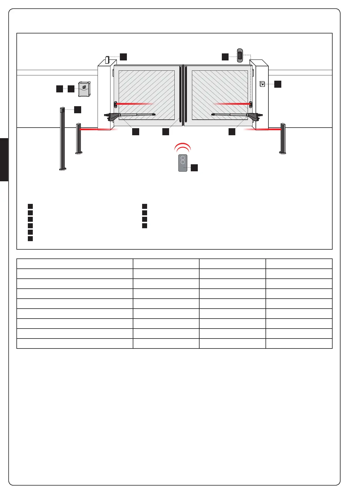
SCHEMA DI INSTALLAZIONE
A
B
C
D
1
2
3
4
5
6
Selector con llave
Fotocélulas con columnas
Selector digital vía radio de columna
Bandas de seguridad
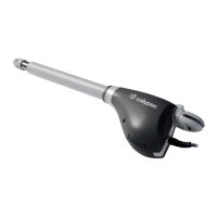
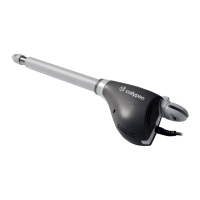
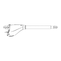
Actuador
Cuadro de maniobras
Emisor
Módulo receptor
Fotocélulas
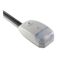
Lámpara de señalización
COMPONENTES ACCESORIOS ADICIONALES
LONGITUD DEL CABLE < 10 metros de 10 a 20 metros de 20 a 30 metros
Alimentación 230/120V 3G x 1,5 mm
2
3G x 1,5 mm
2
3G x 2,5 mm
2
Alimentación motor 230/120V 4G x 1,5 mm
2
4G x 1,5 mm
2
4G x 2,5 mm
2
Fotocélulas (TX) 2 x 0,5 mm
2
2 x 0,5 mm
2
2 x 0,5 mm
2
Fotocélulas (RX) 4 x 0,5 mm
2
4 x 0,5 mm
2
4 x 0,5 mm
2
Selector con llave 2 x 0,5 mm
2
2 x 0,5 mm
2
2 x 0,5 mm
2
Banda de seguridad 2 x 0,5 mm
2
2 x 0,5 mm
2
2 x 0,5 mm
2
Lámpara de señalización 2 x 1,5 mm
2
2 x 1,5 mm
2
2 x 1,5 mm
2
Antena (integrada en la lámpara de señalización) RG174 RG174 RG174
1 1D
3
A
C
2
56
4
 Loading...