ITALIANO
- 4 -
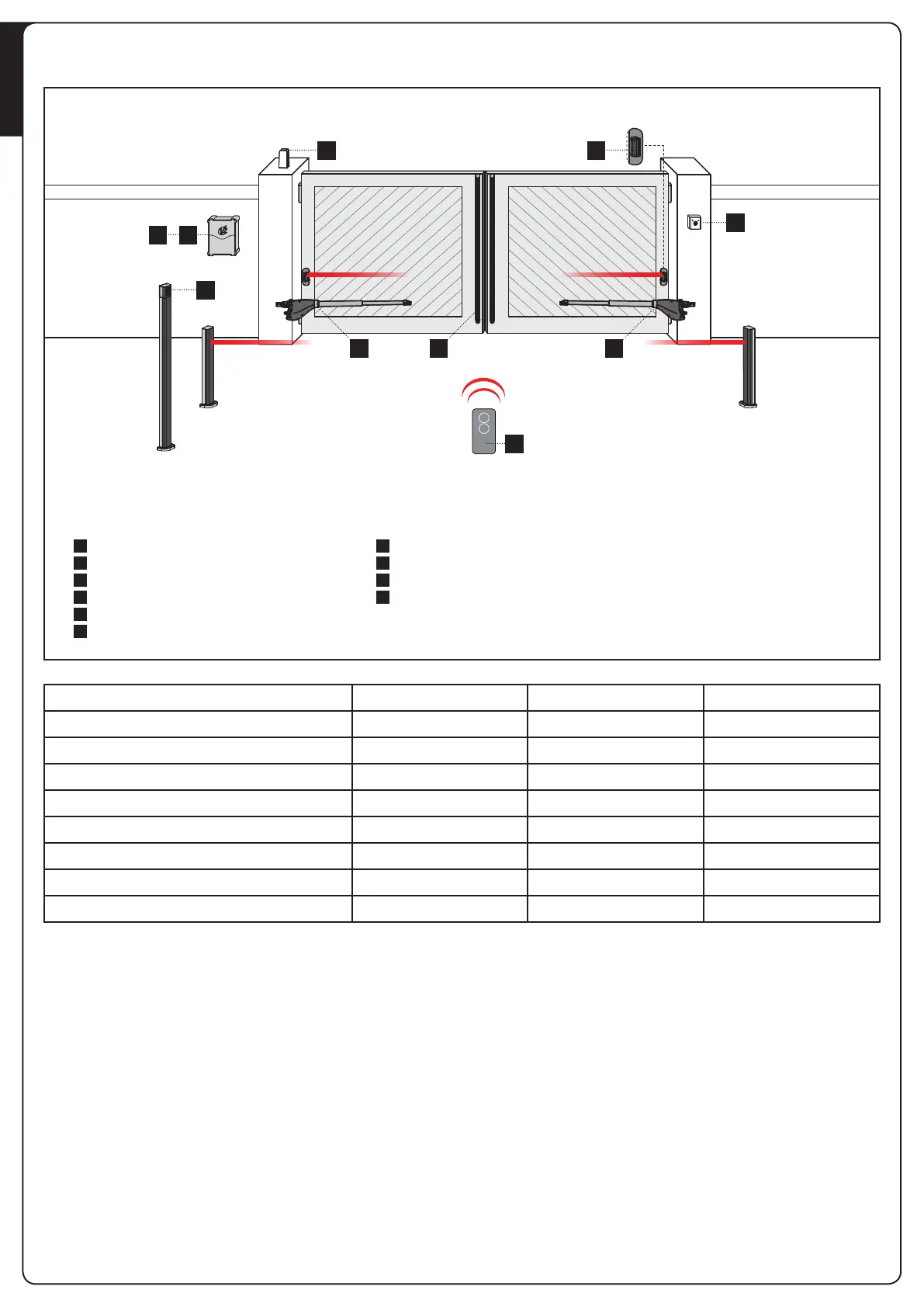
SCHEMA DI INSTALLAZIONE
1 1D
3
A
C
2
56
4
A
B
C
D
1
2
3
4
5
6
Selettore chiave
Fotocellule a colonna
Selettore digitale via radio a colonna
Coste di sicurezza
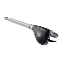
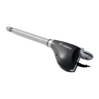
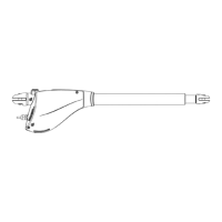
Motore
Centrale di comando
Trasmettitore
Modulo ricevitore
Fotocellule
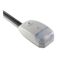
Lampeggiante
COMPONENTI ACCESSORI AGGIUNTIVI
LUNGHEZZA DEL CAVO < 10 metri da 10 a 20 metri da 20 a 30 metri
Alimentazione 230/120V 3G x 1,5 mm
2
3G x 1,5 mm
2
3G x 2,5 mm
2
Alimentazione motore 230/120V 4G x 1,5 mm
2
4G x 1,5 mm
2
4G x 2,5 mm
2
Fotocellule (TX) 2 x 0,5 mm
2
2 x 0,5 mm
2
2 x 0,5 mm
2
Fotocellule (RX) 4 x 0,5 mm
2
4 x 0,5 mm
2
4 x 0,5 mm
2
Selettore chiave 2 x 0,5 mm
2
2 x 0,5 mm
2
2 x 0,5 mm
2
Costa di sicurezza 2 x 0,5 mm
2
2 x 0,5 mm
2
2 x 0,5 mm
2
Lampeggiante 2 x 1,5 mm
2
2 x 1,5 mm
2
2 x 1,5 mm
2
Antenna (integrata nel lampeggiante) RG174 RG174 RG174
 Loading...