DEUTSCH
- 34 -
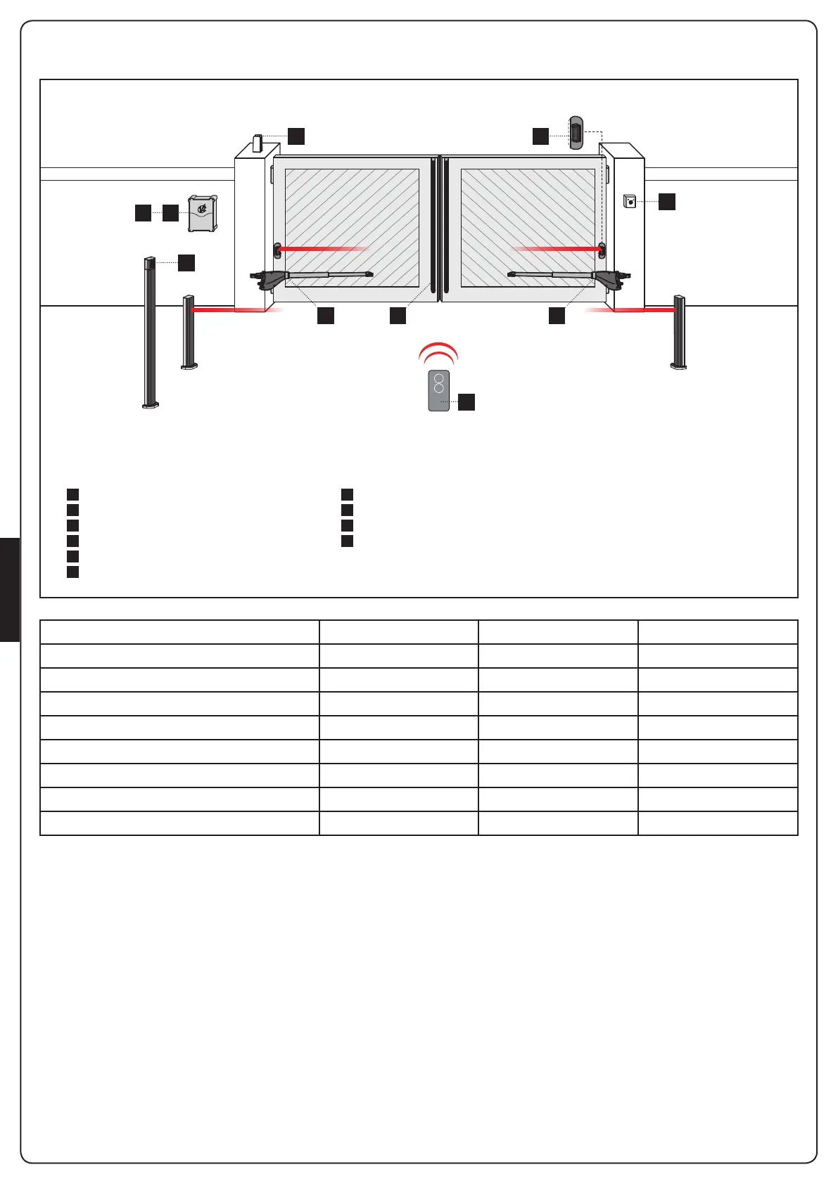
INSTALLATIONSPLAN
A
B
C
D
1
2
3
4
5
6
Schlüsselschalter
Fotozellen auf Säule
Funk-Codetaster, auf Säule
Sicherheitskontaktleisten
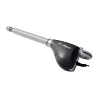
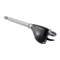
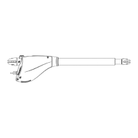
Drehtorantrieb
Steuerung
Handsender
Empfangsmodul
Fotozellen
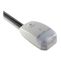
Blinklicht
BAUTEILE ZUSATZZUBEHÖR
KABELLÄNGE < 10 Meter von 10 bis 20 Meter von 20 bis 30 Meter
Spannungsversorgung 230/120V 3G x 1,5 mm
2
3G x 1,5 mm
2
3G x 2,5 mm
2
Spannungsversorgung (Antriebe 230/120V) 4G x 1,5 mm
2
4G x 1,5 mm
2
4G x 2,5 mm
2
Fotozellen (TX) 2 x 0,5 mm
2
2 x 0,5 mm
2
2 x 0,5 mm
2
Fotozellen (RX) 4 x 0,5 mm
2
4 x 0,5 mm
2
4 x 0,5 mm
2
Schlüsselschalter 2 x 0,5 mm
2
2 x 0,5 mm
2
2 x 0,5 mm
2
Sicherheitskontaktleisten 2 x 0,5 mm
2
2 x 0,5 mm
2
2 x 0,5 mm
2
Blinklicht 2 x 1,5 mm
2
2 x 1,5 mm
2
2 x 1,5 mm
2
Antenne (im Blinklicht eingebaut) RG174 RG174 RG174
1 1D
3
A
C
2
56
4
 Loading...