NEDERLANDS
- 40 -
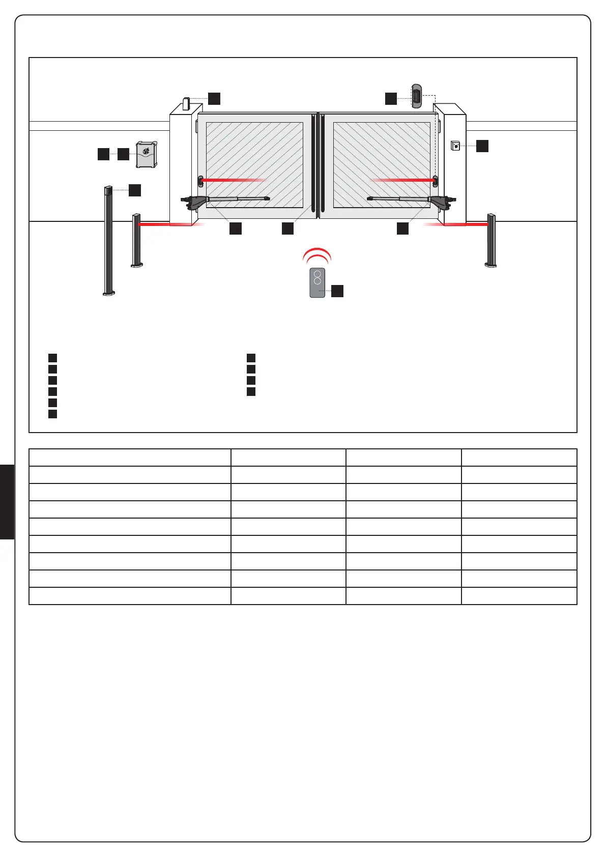
INSTALLATIESCHEMA
A
B
C
D
1
2
3
4
5
6
Sleutelschakelaar
Pijler fotocellen
Digitale radio-schakelaar voor montage op pijler
Veiligheidsbezettingen
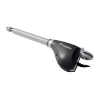
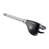
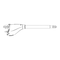
Motor
Besturingseenheid
Zender
Module plug-in ontvanger
Fotocellen
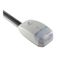
Knipperlicht
ONDERDELEN AANVULLLENDE ACCESSOIRES
TE GEBRUIKEN KABELS < 10 meter van 10 tot 20 meter van 20 tot 30 meter
Voeding 230/120V 3G x 1,5 mm
2
3G x 1,5 mm
2
3G x 2,5 mm
2
Voeding motore 230/120V 4G x 1,5 mm
2
4G x 1,5 mm
2
4G x 2,5 mm
2
Fotocellen (TX) 2 x 0,5 mm
2
2 x 0,5 mm
2
2 x 0,5 mm
2
Fotocellen (RX) 4 x 0,5 mm
2
4 x 0,5 mm
2
4 x 0,5 mm
2
Sleutelschakelaar 2 x 0,5 mm
2
2 x 0,5 mm
2
2 x 0,5 mm
2
Veiligheidsbezettingen 2 x 0,5 mm
2
2 x 0,5 mm
2
2 x 0,5 mm
2
Knipperlicht 2 x 1,5 mm
2
2 x 1,5 mm
2
2 x 1,5 mm
2
Antenne (ingebouwd in het knipperlicht) RG174 RG174 RG174
1 1D
3
A
C
2
56
4
 Loading...