ENGLISH
- 10 -
LOCK
1 2 3 4 5 6 7 8 9 10 11 12
RECEIVER
L1 L2
A1
POWER WORK PAUSE DELAY
A2
L3 L4 L5 L6 L7 L8 L9 L10 L11 K1 K2 K3 K4 K5 K6 K7 K8 K9 K10 N mains L
ANT
START
START STOP EDGE
overload
mains
START P. PHOTO
STOP
START P.
PHOTO
(Photo / Edge Test)
EDGE
COM
24VAC - 3W
GND
OPEN
COM
CLOSE
OPEN
LAMP
Max 40W
NEUTRAL
PHASE
COM
CLOSE
24VAC
COURTESY
LIGHT
CONTACT
M1 M2
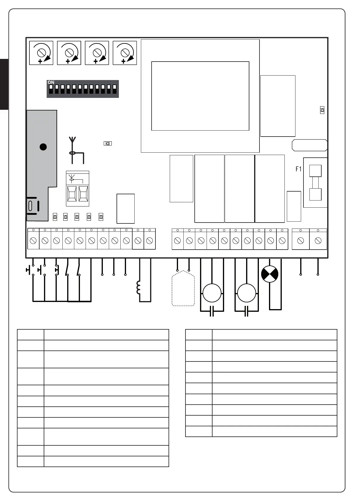
ELECTRICAL CONNECTION
A1 Antenna
A2 Antenna shield
L1 Openingcommandforastandardconnectiondevice
withswitchnormallyopen.
L2 Pedestrianopeningcommandforastandard
connectiondevicewithswitchnormallyopen.
L3 STOPcommand.N.C.switch
L4 Photocell.N.C.switch
L5 Edge.SwitchN.C.orresistiverubberedge
L6 Commandscommon(-)line
L7 - L8 24VACpoweroutputforphotocellsandother
accessories
L8 - L9 PowersupplyforfunctionaltestTXphotocell
L10 - L11 12V electric lock
K1 - K2 Courtesylighttimeractivationswitch
K3 Motor1open
K4 Motor1common
K5 Motor1close
K6 Motor2open
K7 Motor2common
K8 Motor2closed
K9 - K10 230V - 40W / 120V - 40W blinker
N 230V/120Vpowersupply-neutral
L 230V/120Vpowersupply-phase
m PLEASE NOTE: If not used, the normally closed
inputs (STOP, PHOTO, EDGE) must be jumpered with the
commands common line COM (-)
 Loading...