ENGLISH
- 11 -
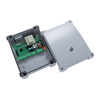
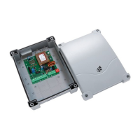
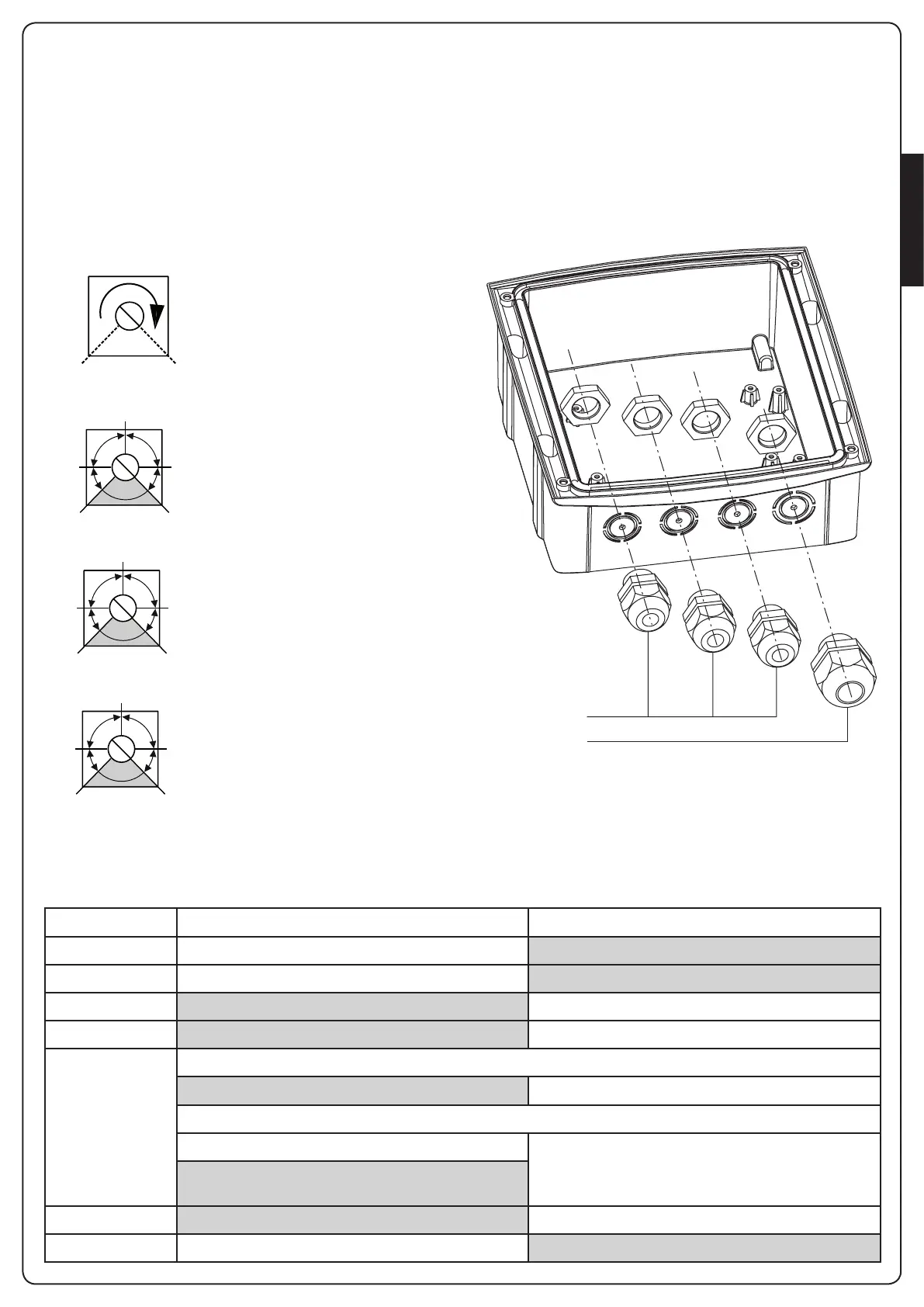
CABLE GLAND ASSEMBLY
Thecasingcanaccept4cableglandsinthespecialeasy-break
housings.Thetypeofcableglandisindicatedinthegure.
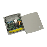
m PLEASE NOTE:
• Removetheelectroniccircuitboardbeforedrillthecasing.
• Drillthecontainerusingasuitablysizedcutter,accordingtothe
dimensionsofthecablegland.
• Fixthecableglandsusingthespecialnuts.
PG9 - PG11
PG9 - PG11 - PG16
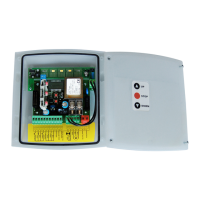
CONTROL UNIT INDICATORS (LEDs)
ThehighlightedboxesindicatethestateoftheLEDswhenthegateisresting.
ADJUSTMENT OF THE POWER AND
OPERATIONAL TIMES
Thepowerandoperatingtimesmaybeadjustedbymeansof4
trimmers located on the control unit:
m PLEASE NOTE: it is recommended that operating times
be set with the slow down function disabled (DIP 5 OFF).
m WARNING: the adjustment of times has to be made
when the gate is still
POWER
MIN MAX
WORK
50”
18”
2”
2”
45”
PAUSE
150”
30”
2”
2”
90”
DELAY
90”
15”
0
0
45”
POWER:motorpower
WORK:motoroperatingtime
(2-50seconds)
PAUSE:pausetimebefore
automatic re-closure
(2-150seconds).
DELAY:timedelaybetweenthe
twogateleaves(0-90seconds).
LED ON OFF
START STARTinputclosed STARTinputopen
START P. STARTP.inputclosed STARTP.inputopen
STOP STOPinputclosed STOPinputopen
PHOTO PHOTOinputclosed PHOTOinputopen
EDGE Standard edge
EDGEinputclosed(edgenotpressed) EDGEinputopen(edgepressed)
Resistive rubber edge
EDGEinputclosed(edgepressed) EDGEinputopen(fault)
EdgeNOpressed:8K2betweenEDGEinputand
common(-)
mains Controlunitpowered-up ControlunitNOTpowered-up
overload Accessorypowersupplyoverload Accessorypowersupplywithinnormaloperationallimits
 Loading...