www.vac.se
92026r15
V200 POSITIONER
10
R
S
P
L
I
T
R
A
N
G
E
9
0
°
D
0
%
9
0
°
L
I
N
1
0
0
%
1
0
0
%
1
8
0
°
L
I
N
5
0
%
0
%
0
%
9
S
P
L
I
T
R
A
N
G
E
9
0
°
D
R
0
%
5
0
%
1
8
0
°
L
I
N
1
0
0
%
1
0
0
%
9
0
°
L
I
N
0
%
B
R
S
P
L
I
T
R
A
N
G
E
9
0
°
D
0
%
9
0
°
L
I
N
1
0
0
%
1
0
0
%
1
8
0
°
L
I
N
5
0
%
0
%
2.5 Cam
The V200 is standard shipped
with the C1-cam, factory set
for 90° ±1°, direct (CCW) turning.
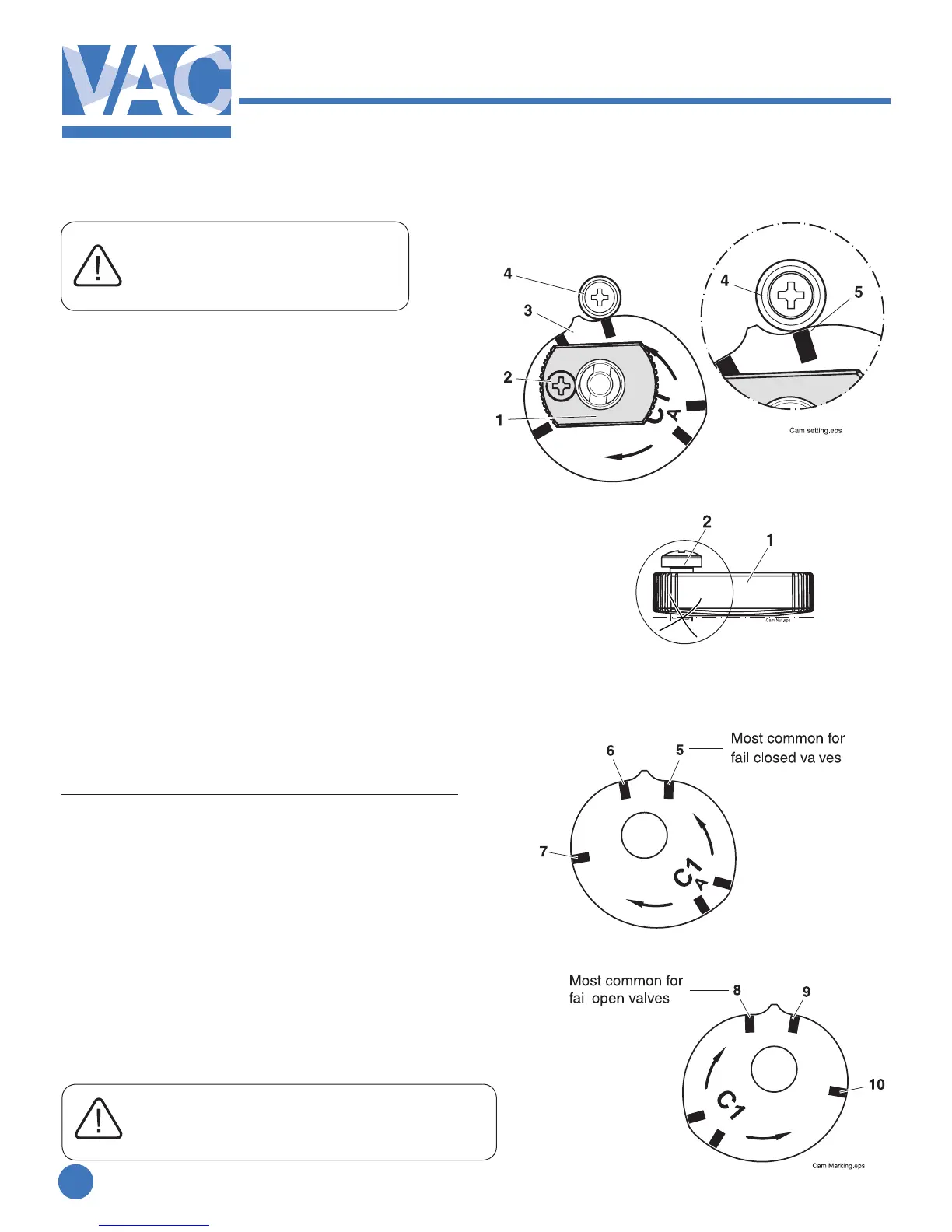
2.5.1 Adjustments
Remove the front cover and indicator.
(see page 15)
1. Loosen the locking screw(2) and the cam
nut(1).
2.Strokethevalve/actuatortothestop/end
position at 0% input.
3. Turn the cam(3) so that the index mark(5)
for the selected curve aligns with the ball
bearing(4). A small gap between the roller and
the cam tip is desirable.
4. Tighten the cam nut by hand(1).
Check that the locking screw(2) is still loose.
(if not, loosen the locking screw slightly and
tighten the nut again).
5. Tighten the locking screw(2).
Do not tighten cam nut with screw(2) down.
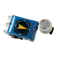
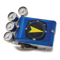
2.5.2 Cam specications C1
Indexmark/Startingpointofrotation*
5. 90° Linear 0-100% CCW
6. 180° Linear 0-100% CW
6. 90° Linear 0-50% CW split range
7. 90° Linear 50-100% CW split range
8. 90° Linear 0-100% CW
9. 180° Linear 0-100% CCW
10. 90° Linear 0-50% CCW split range
11. 90° Linear 50-100% CCW split range
*Increasingsignalrotation.
MostvalvesrotateCWtoclose/CCWtoopen
When eld reversing action of positioner
tubing must be reversed as well
(see page 7 and 8)