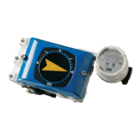
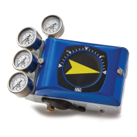
V200 POSITIONER
www.vacaccessories.com
92026r15
3
1 INTRODUCTION .................................................................................. 4
1.1 Principle of Operation .............................................................. 4
1.2 ProductIdentication ............................................................... 4
1.3 Air quality recommendations ................................................... 5
1.4 Safety Instructions ................................................................... 5
2 INSTALLATION .................................................................................... 6
2.1 Connections ............................................................................ 6
2.2 General mounting instructions ................................................ 7
2.2.1 Rotary actuators ...................................................................... 7
2.2.2 Linear actuators ...................................................................... 7
2.3 Installation instructions for rotary actuators ............................. 8
2.3.1 Double acting .......................................................................... 8
2.3.2 Single acting ............................................................................ 8
2.4 Installation instructions for linear actuators ............................. 9
2.4.1 Double acting .......................................................................... 9
2.4.2 Single acting ............................................................................ 9
2.5 Cam ......................................................................................... 10
2.5.1 Adjustments ............................................................................ 10
2.5.2 Camspecications .................................................................. 10
2.6 Spindle(Drive) ......................................................................... 11
2.6.1 Spindle removal ...................................................................... 11
2.6.2 Spindle mounting .................................................................... 11
2.7 Installing IP converter .............................................................. 12
2.7.1 Internal IP converter ................................................................ 12
2.8 4-20 mA connection ................................................................ 13
2.8.1 Connecting the control signal .................................................. 13
2.8.2 Checking the control signal ..................................................... 13
2.8.3 Bench test with calibrator ........................................................ 13
2.8.4 Checking the IP internal circuit ................................................ 13
2.9 Calibration ............................................................................... 14
2.10 Front cover and Indicator ........................................................ 15
2.10.1 Removing the front cover ........................................................ 15
2.10.2 Removingatindicatorcover .................................................. 15
2.10.3 Removing Dome indicator cover ............................................. 15
2.10.4 Changing the sealings in the front cover ................................. 15
2.10.5 Installingatindicatorcover .................................................... 16
2.10.6 Installing Dome indicator cover ............................................... 16
2.10.7 Removing the indicator ........................................................... 16
2.11 MainsupplylterforIPconverter ............................................ 17
2.12 Pilot valve remove and install .................................................. 18
---- Intentionally blank ................................................................... 19
3 SPARE PARTS ................................................................................... 20
3.1 Exploded drawing .................................................................... 20
3.2 Spare parts list ........................................................................ 21
4 SPECIFICATIONS............................................................................... 22
4.1 SpecicationsV200 ................................................................. 22
5 DIMENSION ........................................................................................ 23
5.1 V200P/Estd ........................................................................... 23
CONTENTS