www.vac.se
92026r15
V200 POSITIONER
6
2. INSTALLATION
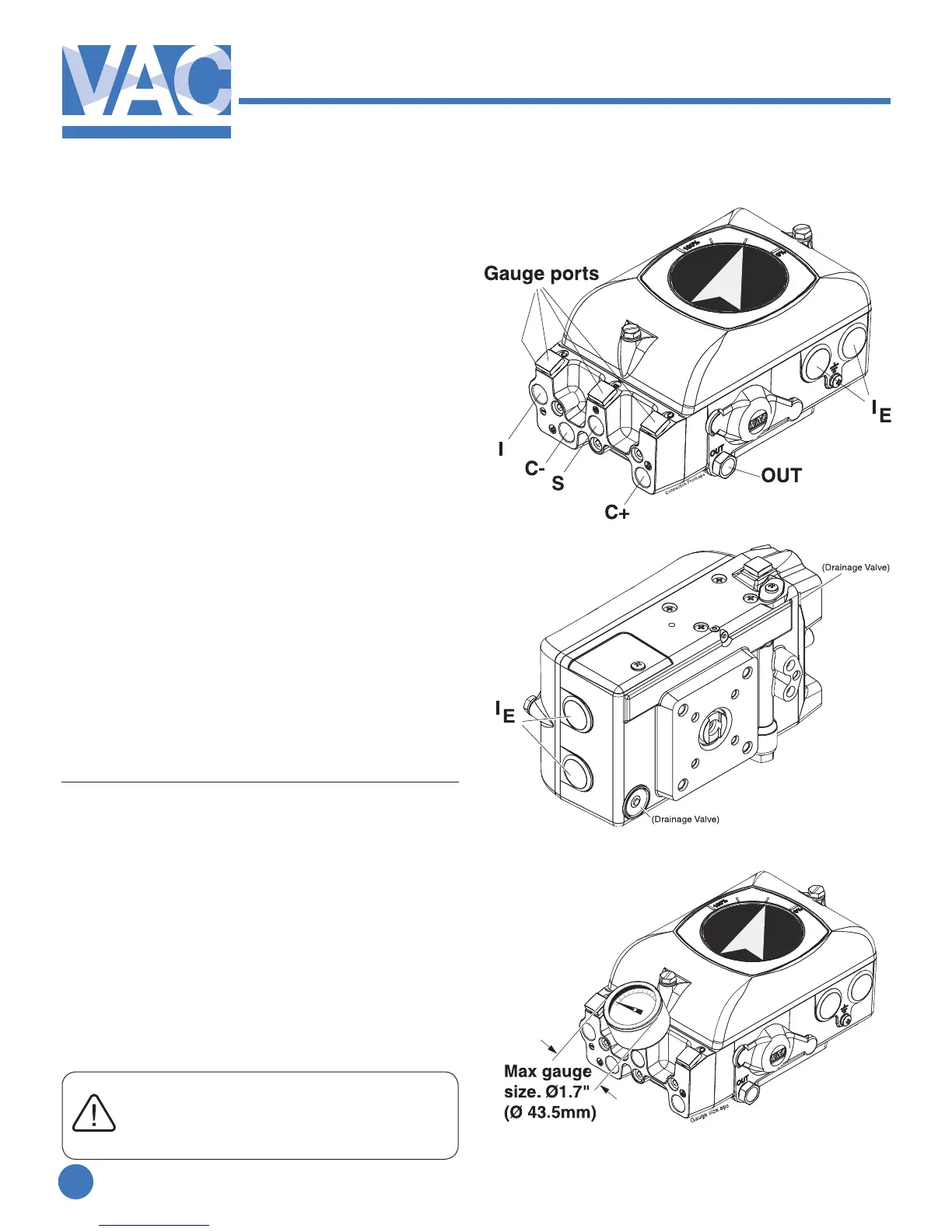
2.1 Connections
S–Supplyair
V200P:max.145PSI/1MPa
V200E:23-145PSI/0,15-1MPa
I–Input,pressuresignal
V200P:3-15PSI/20-100kPa
V200E:Plugged
I
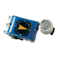
E
–Input,currentsignal
V200E:4-20mA(Rimax250ohm)
V200P:Plugged
C+ -Actuatorconnection+stroke
C- - Actuator connection - stroke
OUT - All air from the actuator, IP and posi-
tioner is vented through this port.
Standardequippedwithabugscreen/silencer
Airconnectionsformale1/4”NPTorG1/4”.
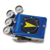
Gaugeconnectionsformale1/8”NPTorG1/8”.
Cableentryformale1/2”NPTorM20cablet-
tings.
G threads are indicated by an engraved G
on the air connection side of the positioner.
GaugeportsI,C+,C-andSarefactoryplugged.
Remove plugs and replace with gauges.
The IP connection must be plugged in
V200E.
The IE entrys should be plugged in
V200P