Vacon Plc Phone: +358-201 2121 Fax:+358-201 212 205
Service: +358-40-8371 150 E-mail: vacon@vacon.com
Page 12 Vacon
Pump and fan control with autochange
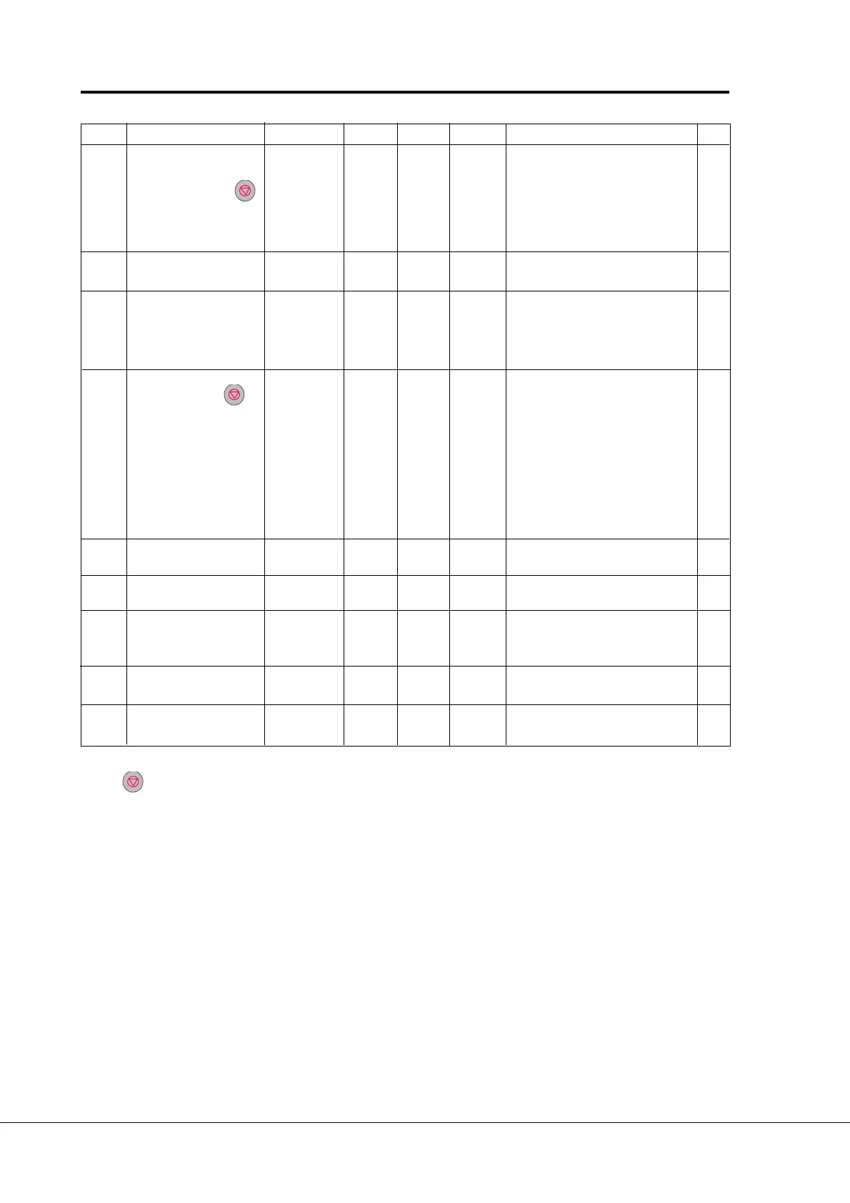
Code Parameter Range Step Default Custom Description Page
2. 26 Direct frequency 0—410 0 = U
in
signal (control board) 24
reference, source B 1 = I
in
signal (control board)
2 = Set reference from the panel
(reference r1)
3 =
Signal from internal motor pot.
4 =
Signal from internal motor pot.
reset if Vacon unit is stopped
2. 27 Source B reference 0—par.2. 28 1 Hz 0 Hz Selects the frequency that corres- 24
scaling minimum value ponds to the min. refer. signal
2. 28
Source B reference
par.2. 28 1 Hz 0 Hz Selects the frequency that 24
scaling maximum value —f
max
corresponds to the max.
reference signal
0 = Scaling off
>0 = Scaled maximum value
2. 29 PI-controller 0—717 0 = U
in
signal (control board) 25
reference 2 1 = I
in
signal (control board)
2 = Set reference from the panel
(reference r2)
3 =
Signal from internal motor pot.
4 =
Signal from internal motor pot.
reset if Vacon unit is stopped
5 = Option board Ain1-signal
6 = Option board Ain2-signal
7 = Set reference from the panel
(reference r3)
2. 30 Option board Ain1 signal 0—1 1 0 0 = Not inverted 25
inversion 1 = Inverted
2. 31 Option board Ain1 signal 0—10s 0.01s 0.1s 0 = No filtering 25
filter time
2. 32 Option board Ain2 signal 0—210 0 = 0—20 mA 25
signal range 1 = 4—20 mA
2 = 0—10 V
2. 33 Option board Ain2 signal 0—1 1 0 0 = Not inverted 25
inversion 1 = Inverted
2. 34 Option board Ain2 signal 0 —10s 0.01s 0.1s 0 = No filtering 25
filter time
Note! = Parameter value can be changed only when the frequency converter is stopped (Continues)
 Loading...


