Page 1 4 (1 5 ) Vacon
I/ O-expander board installation (Vacon CXS-range)
Vacon Plc Tel: +3 58 -2 01 2 1 2 1 Fax: + 3 5 8-2 01 2 1 2 20 5
Service: +3 5 8 -4 0 -8 37 1 1 50 E-mail: vacon@vacon.com
http:/ / w ww.vacon.com
4.4 Vacon CX103OPT
*) N OTE! Thermistor input (terminals 2 2 1 and 2 2 2 ) must be shorted if not used.
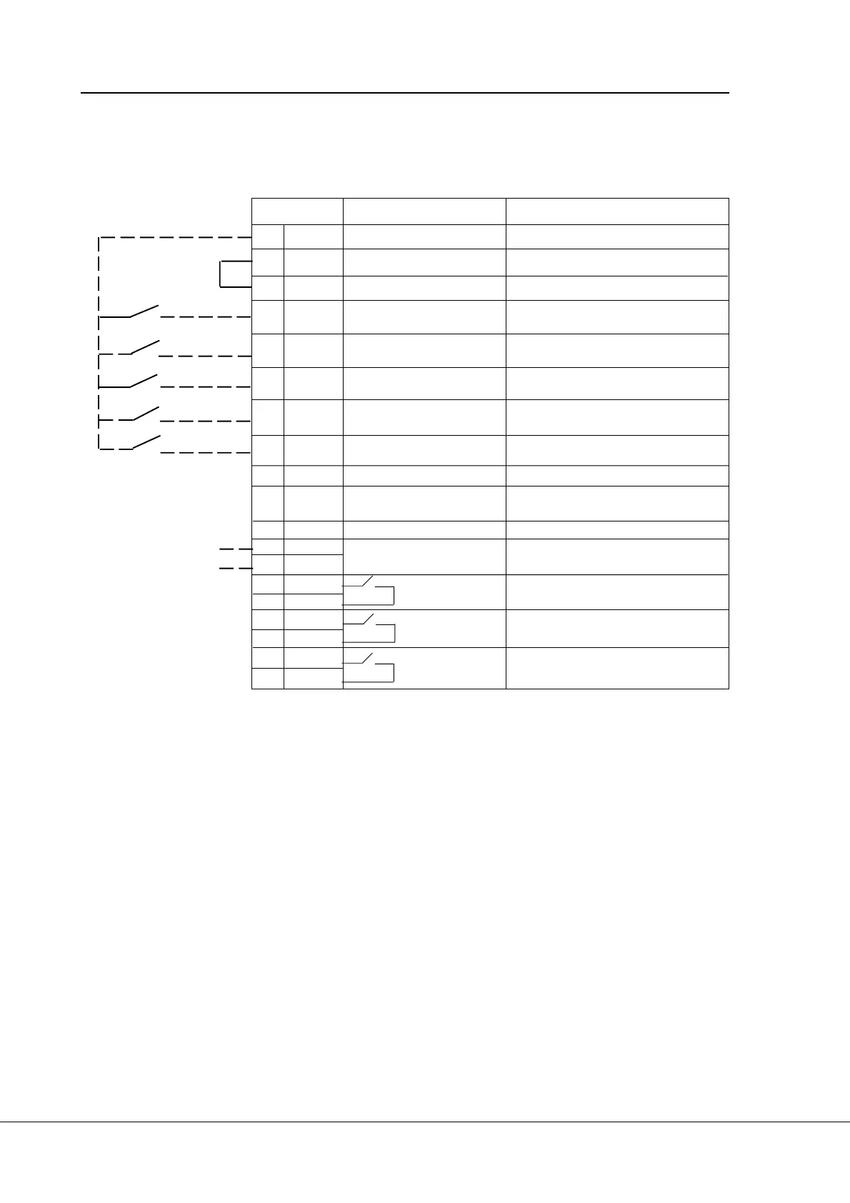
Figure 4 -4 Control connections of Vacon CX1 0 3 O PT.
Terminal Signal Description
206 +2 4 V C ontrol voltage output Voltage for sw itches, etc. max. 5 0 mA
207 GN D I/ O ground Ground for reference and controls
208 CMC Common for DIC1 -DIC5 Connect to G N D or + 2 4 V
209 DIC1 External fault Contact open = no fault
(closing contact) Contact closed = fault
210 DIC2 Run disable Cont. open = start of motor enabled
Cont. closed= start of motor disabled
211 DIC3 Acceler. / Decel. time Contact open = time 1 selected
selection Contact closed = time 2 selected
212 DIC4 Jogging speed selection Contact open = no action
Contact closed = jogging speed
213 DIC5 Fault reset Contact open = no action
Contact closed = fault reset
214 GN D I/ O ground
2 15 I
out
+ Analogue output Programble
0 —2 0 mA/ R
L
max. 50 0 Ω (M otor current as default value)
221 TI+ Thermistor input
2 2 2 TI -
2 2 3 RO 3 / 1 Relay output 3 READY
2 2 4 RO 3 / 2
2 2 5 RO 4 / 1 Relay output 4 RUN
2 2 6 RO 4 / 2
2 2 7 RO 5 / 1 Relay output 5 FAULT
2 2 8 RO 5 / 2
Signal from
motor thermistors * )
 Loading...


