25ecoTEC plus 937 installation and maintenance manual
10
11
12
13
9
8
7
6
1
2
3
4
5
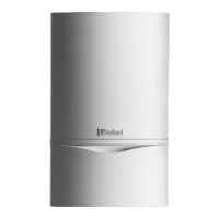
Fig. 4.9 Flow and return heating connections
• Remove the isolation valves with union nuts, olives
and fibre washers from the box of accessories for the
combi boiler.
• Insert the fibre washer (1) and screw the isolation
valve (2) onto the return pipe connection on the
combi boiler.
• Insert the fibre washer (10) and screw the isolation
valve (9) with the fitted flexible hose (13) onto the
flow connection of the combi boiler.
• Fit the O-ring seal (12) to the non-return valve (11).
h
Note!
Lay the filling loop hose (13) above the pipework
elbows.
• Push the union nuts (4) and (7) with olives (3) and (8)
onto the pre-shaped 22 mm pipes (5) and (6).
• Push the pipes (5) and (6) into the isolation valves up
to the stop. Tighten the union nuts in this position.
• Fit the handle for the filling loop to the cold water
isolation valve (9) with a countersunk screw.
a
Caution!
Please note that, when fitting a hydraulic
diverter the diameter of the connection lines
between the unit and the diverter must not be
greater than 22 mm.
Ø max. 22 mm
Fig. 4.10 Diameter of the connection lines when using a
hydraulic diverter
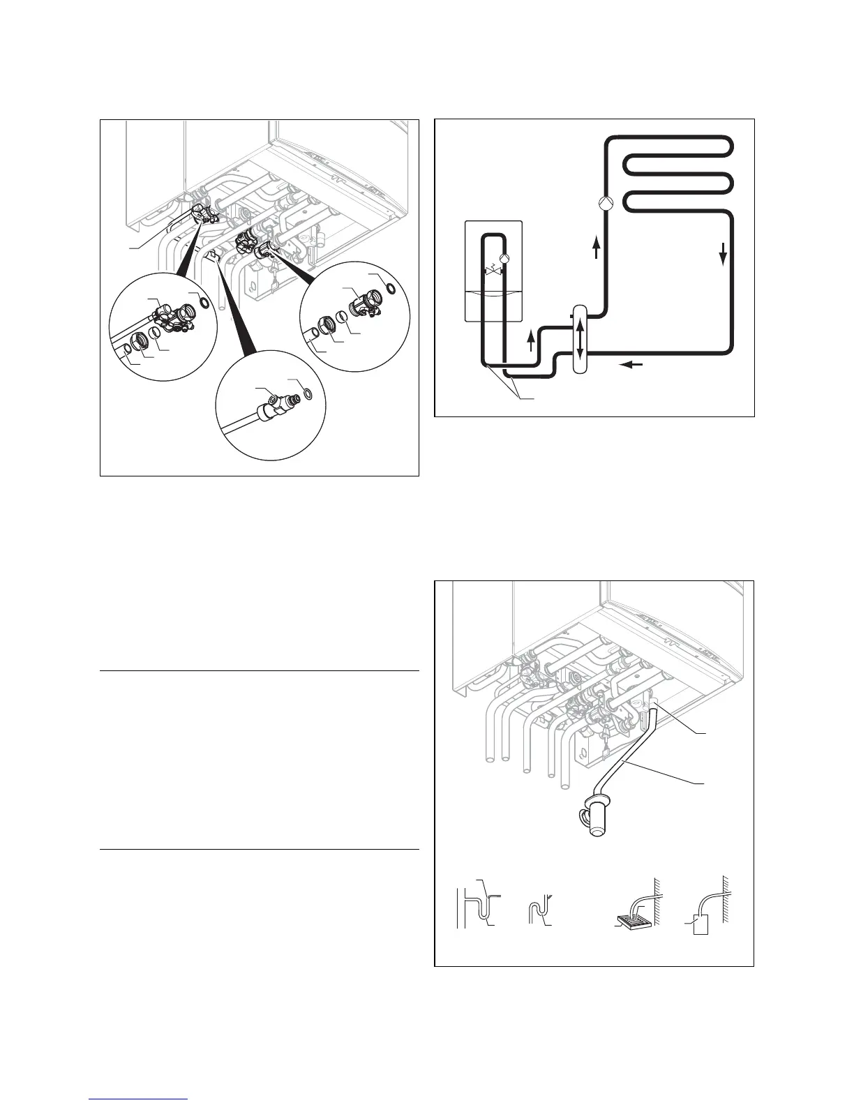
4.15 Condensate drain
The combi boiler is equipped with a condensate siphon.
(The filling height is 145 mm.) The siphon collects the
condensate in a vessel with a capacity of approx. 200 ml
and feeds the entire contents to the drain pipe. This
minimises the risk of the drain pipe freezing up.
1
2
7
d
c
6
5
a
3
4
3
b
Fig. 4.11 Installing the condensate drain
Sequence of operations during installation 4
 Loading...