ecoTEC plus 937 installation and maintenance manual54
Second diagnostic level
• As described above in the first diagnostic level, scroll
through to the diagnosis number d.97.
• Change the displayed value to 17 (Password) and push
the button "i".
You are now in the second diagnostic level where all
information from the first diagnostic level (see Table 8.2)
and the second diagnostic level (see Table 8.3) is
displayed.
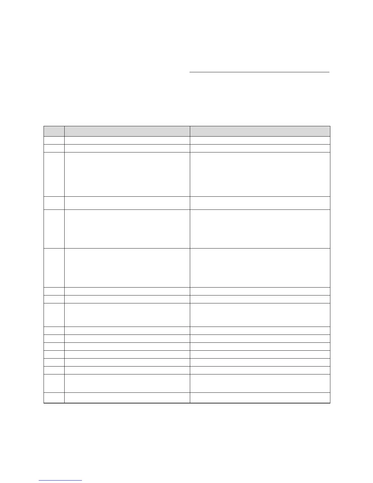
Display Meaning Displayed value/settable value
d.17 Heating flow/return regulation changeover 0 = flow, 1 = return (factory setting: 0)
d.18 Pump mode (return flow) 0 = overrun, 1 = continuous, 2 = winter (Factory setting: 0)
d.19 Operating modes of the two-speed heating pump 0 = Pre-ignition speed 1, Hot water or heating speed 2, overrun
speed 1
1 = Pre-ignition speed 1, hot water speed 2, heating speed 1,
overrrun speed 1
2 = Like 1 but speed in heating mode dependant on heating part
load d.0 (if d.0 is below 60 % of full load, then pump speed 1,
otherwise speed 2); Factory setting 2)
3 = Always speed 2
d.20 Maximum set value for external cylinder target
temperature (system boilers only)
Setting range: 50 °C to 70 °C (Factory setting 65 °C)
d.27 Switching relay 1 on the accessories module 1 = Circulation pump (factory setting)
2 = Ext. Pump
3 = External cylinder charging pump
4 = Flue gas flap/extractor hood
5 = External gas valve
6 = External error message
d.28 Switching relay 2 on the accessories module 1 = Circulation pump
2 = Ext. pump (factory setting)
3 = External cylinder charging pump
4 = Flue gas flap/extractor hood
5 = External gas valve
6 = External error message
d.50 Offset for minimum fan speed in upm/10, adjustment range: 0 to 300
d.51 Offset for maximum fan speed in upm/10, adjustment range: -99 to 0
d.58 Activation solar pre-heat function Setting range: 0 to 3
0 = solar post-heating deactivated (factory setting)
3 = Activation hot water target value min = 60 °C for solar pre-
heat
d.60 Number of safety temperature limiting switch-offs Quantity
d.61 Number of unsuccessful ignitions Number of successful ignitions in the last attempt
d.64 Average ignition duration in seconds
d.65 maximum ignition duration in seconds
d.68 Successful ignitions at the first attempt Quantity
d.69 Successful ignitions at the second attempt Quantity
d.70 Setting the diverter valve position 0 = Normal mode (factory setting)
1 = mid-position
2 = Permanent heating position
d.71 Maximum flow temperature knob setting Adjustment range in °C 40 to 85 (Factory setting: 75)
Table 8.3 Diagnostic codes in the second level
(continuation see next page)
Scroll and change values and exit diagnosis mode as
described in the first diagnosis level.
h
Note!
If you push the buttons "i" and "+" again within
4 minutes after leaving the second diagnosis
level you will go directly to the second
diagnosis level without having to enter the
password again.
8 Troubleshooting
 Loading...