12 Installation and maintenance instructions ecoTEC plus 0020244998_04
6 Set-up
6.1 Checking the scope of delivery
▶ Check that the scope of delivery is complete and intact.
6.1.1 Scope of delivery
Num-
ber
Description
1
Heat generator
1 Shift-load cylinder
1 Lower cover of shift-load cylinder
1 Kit for wall installation:
1 - Product retainer
1 - Bag with small parts
1 Shift-load cylinder installation kit containing the follow-
ing:
2 - Connection pipe (heating flow and return)
1 - Shift-load cylinder-in connection pipe
1 - Shift-load cylinder-out connection pipe
1 - Drain hose for the expansion relief valve on the shift-
load cylinder
1
- Bag with small parts
1
Heat generator installation kit containing the following:
1
- Connector for the expansion relief valve on the boiler
1 - Connector 15 mm (gas)
1
- Gas compression joint, 15 mm
4 - Service valve
1 - Hot water connector
1 - 22 mm connection piece (heating flow and return
connection)
2
- Bag with small parts
1 Lower cover of heat generator
1
Installation template
1
Condensate drain hose
1
Enclosed documentation
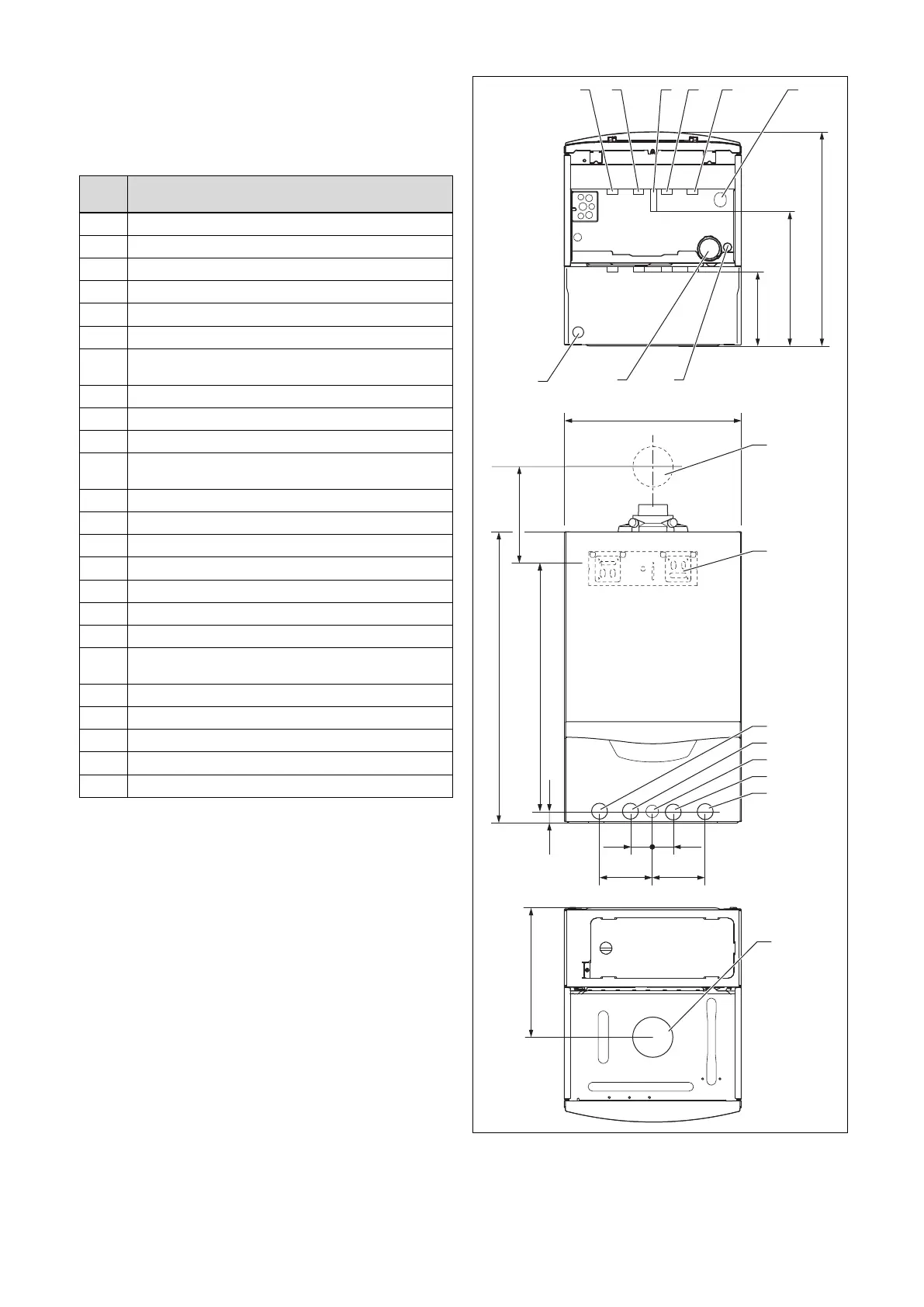
6.2 Dimensions
720
20
35 35
624
323
180
323
624
100100
440
A
2
1
8
3
4
5
6
7
765
43
10 9
11
12
1 Wall duct for flue pipe
2 Product holder
3 Heating flow (22 × 1.5
diameter)
4 Hot water connection
(15 × 1.5 diameter)