48 Installation and maintenance instructions 0020244997_07
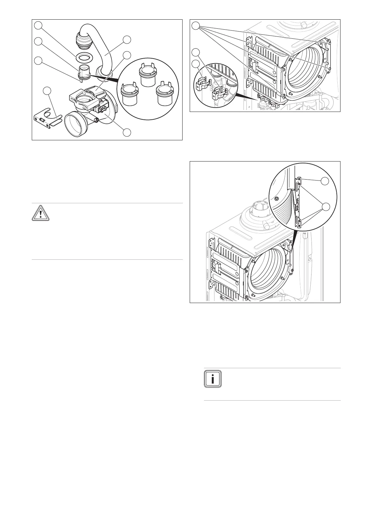
5. Remove the gas connection pipe (1) from the Venturi
(3) by removing the clamp (4) and pulling the gas con-
nection pipe out vertically. Dispose of the seal (7).
6. Pull the gas injector (6) straight off, and keep it for re-
use.
7. Check whether the Venturi is free of residue at the gas
inlet side.
Caution.
Risk of material damage to the product.
Lubricant can block function-related channels
in the Venturi.
▶ Do not use lubricant when installing the
gas restrictor.
8. Ensure that you use the correct gas injector (colour
coding and position of pins on the underside of the gas
injector). The colour of the gas injector must match the
colour of the coding resistor on the PCB.
9. Insert the gas injector for the gas group in question
into the new Venturi (yellow: G20 natural gas, grey:
Liquefied petroleum gas).
10. When inserting the gas injector, ensure that the gas in-
jector is correctly aligned using the indicated position
marks on the upper side of the Venturi and also the po-
sitioning pins (5) on the underside of the gas injector.
11. Refit the components in the reverse order. Use new
seals for this.
12. After installing the new Venturi, carry out a gas setting.
(→ Page 36)
13. If you cannot adjust the CO2 content, the gas injector
has been damaged during installation. In this case,
replace the gas injector with an appropriate spare part.
14. Perform a gas family check. (→ Page 33)
13.6.5 Replacing the heat exchanger
1. Drain the product. (→ Page 44)
2. Remove the compact thermal module. (→ Page 42)
3. Detach the condensate discharge hose from the heat
exchanger.
4. Remove the clamps (2) and (3) from the flow connec-
tion and the return connection.
5. Detach the flow connection.
6. Detach the return connection.
7. Remove two screws (1) on each of the two retainers.
8. Remove the lower three screws (2) on the rear section
of the retainer.
9. Swing the retainer to the side around the top screw (1).
10. Pull the heat exchanger downwards and to the right,
and remove it from the product.
11. Install the new heat exchanger in reverse order.
12. Replace the seals.
Note
Instead of grease, use only water or com-
mercially available soft soap to aid installa-
tion.
13. Insert the flow and return connections into the heat
exchanger as far as they will go.
14. Make sure that the clamps are seated correctly on the
flow and return connections.
15. Install the compact thermal module. (→ Page 44)
16. Fill and purge the product and, if necessary, the heat-
ing installation. (→ Page 35)

 Loading...


