Hydraulics installation 5
0020250180_00 geoTHERM Installation and maintenance instructions 17
▶ Inform the end user about the measures required for frost
protection.
5.6.2 Filling/refilling the heating installation
1. Open all of the thermostatic valves on the heating in-
stallation and, if required, all other isolation valves.
2. Check all of the connections and the entire heating in-
stallation for leaks.
3. To remove air pockets from the heating installation, use
a filling pump to rinse the heating installation. To do
this, fill the heat pump via the return line and allow the
water to flow out via the flow line.
5.7 Filling and purging the brine circuit
5.7.1 Mixing the brine fluid
The brine fluid consists of water mixed with a concentrated
antifreeze. The brine fluids that may be used differ greatly
from region to region. For more information, contact the re-
sponsible authorities.
Only ethylene glycol in the specified ratio is authorised by
Vaillant as a brine fluid for operating the heat pump.
Alternatively, suitable ready-mixed fluids for heat pumps can
be ordered from Vaillant.
▶ Carefully mix ethylene glycol with water.
– Ratio of ethylene glycol to water: 3:7
◁ This results in an aqueous solution with 30% vol.
ethylene glycol.
◁ The brine fluid is protected against frost.
– Frost protection for the brine fluid: −16 … −14 ℃
▶ Check the mixture ratio of the brine fluid.
– Working materials: Refractometer
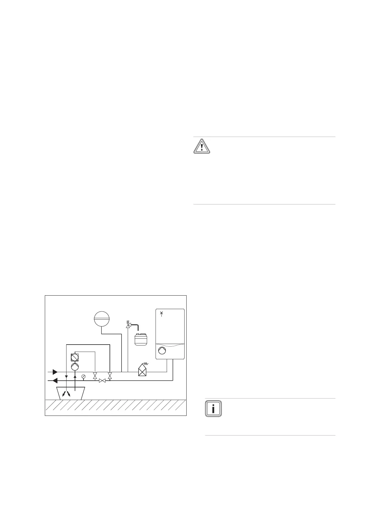
5.7.2 Filling the brine circuit
71
66
48
62
42a
63
61
33
67
65
A
B
69
29
37
29 Brine pump
33 Dirt filter
37 Automatic air separator
42a Expansion relief valve
48 Pressure gauge (op-
tional)
61 Stop valve
62 Stop valve
63 Stop valve
65 Brine collecting con-
tainer
66 Brine container
67 Filling pump
69 Purging screws
71 Expansion vessel
A From the heat source
to the heat pump (hot
brine)
B From the heat pump to
the heat source (cold
brine)
1. Install a dirt filter (33) in the pressure line.
2. Connect the filling pump's pressure line to the isolation
valve (61).
3. Close the isolation valve (63).
4. Open the isolation valve (61).
5. Connect a hose, which leads to the brine fluid, to the
isolation valve (62).
6. Open the isolation valve (62).
Caution.
Risk of material damage caused by an
incorrect filling direction.
If you fill the brine pump against the direction
of flow, this may lead to a turbine effect which
can damage the pump's electronics.
▶ Ensure that the brine pump is filled in the
direction of flow.
7. Use the filling pump (67) to pour the brine fluid from the
brine container (66) into the brine circuit.
– Brine fluid: Ethylene glycol/water ratio: 3/7
8. If you choke the filling pump, you can reduce the air
ingress into the brine circuit.
5.7.3 Purge the brine circuit
1. Start up the filling pump (67) in order to fill and rinse the
brine circuit.
2. Allow the filling pump (67) to run for at least 10 minutes
in order to fill and rinse the circuit sufficiently.
3. Then close the isolation valves (61) and (62) and switch
off the filling pump (67).
4. Open and close the purging valves (69) on the heat
pump and check whether air is still escaping.
5. Purge the heat pump completely in order to prevent
its functioning from being impaired by air in the brine
circuit.
6. Place a silicone hose (5 mm diameter) on the purging
valves and catch the brine fluid in a bucket.
7. If required, repeat this rinsing process.
8. Open the isolation valve (63).
5.7.4 Building up pressure in the brine circuit
1. Use the filling pump (67) to pressurise the brine circuit.
Note
To operate the brine circuit without any prob-
lems, a filling pressure of 0.15 MPa (1.5 bar)
is required. The expansion relief valve opens
at 0.3 MPa (3 bar).
2. Read off the pressure on the manometer.

 Loading...


