6 Electrical installation
20 Installation and maintenance instructions geoTHERM 0020250180_00
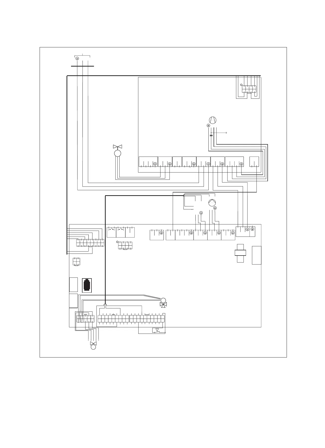
6.4 Wiring diagrams
p
High-pressure switch
X23 X21
X22
X25
X24
X20
LN
230V~
24=
S20
24=
X1
X1 1
LN
230V~
X16
LN
230V~
X13
LN
230V~
C
X15
ON
230V~
X700
LL
230V~
X14
LN
230V~
X100
-
+
BUS
S21
1
1
X20
8
7
2
1
3
4
5
6
12 567843
Building
circuit pump
L
N
Electronic expansion valve
M
Environ-
N
L
X2
Orange
Yellow
Grey
Black
Red
mental
circuit pump
GNDPWM1
PWM2GND
SSM1
SSM2
PWM2 PWM1
GND & SSM 1SSM2
123
45678910
11121314
151617181920
123456
789
11121314
15161718
10
12345
678910
12
34
12
910
34
11 12
56
13 14
78
15 16
12
56
34
78
Relay PCB
Main PCB
X700
L L
230V~
C
X70
RN
230V~
X1C
LN
230V~
X19
L L
230V~
X17
LN
230V~
X1A
LN
230V~
X1B
LN
230V~
L
X18
L
230V~
S
R
C
Compressor
Operating
capacitor
M
BA
N
O
S
52
230V~
LN
X12
F1
X51
X40
X30
Yellow
Blue
Brown
Red
M
3-way mixer
Relay PCB
X700 Compressor safety relay
X70 Compressor
X1A —
X1B Power supply
X1C Main PCB mains connection transfer
X17 Cooling active signal, thermostatic radiator valve
switch
X18 —
X19 —
X20 Main PCB control line

 Loading...


