Appendix
0020250180_00 geoTHERM Installation and maintenance instructions 49
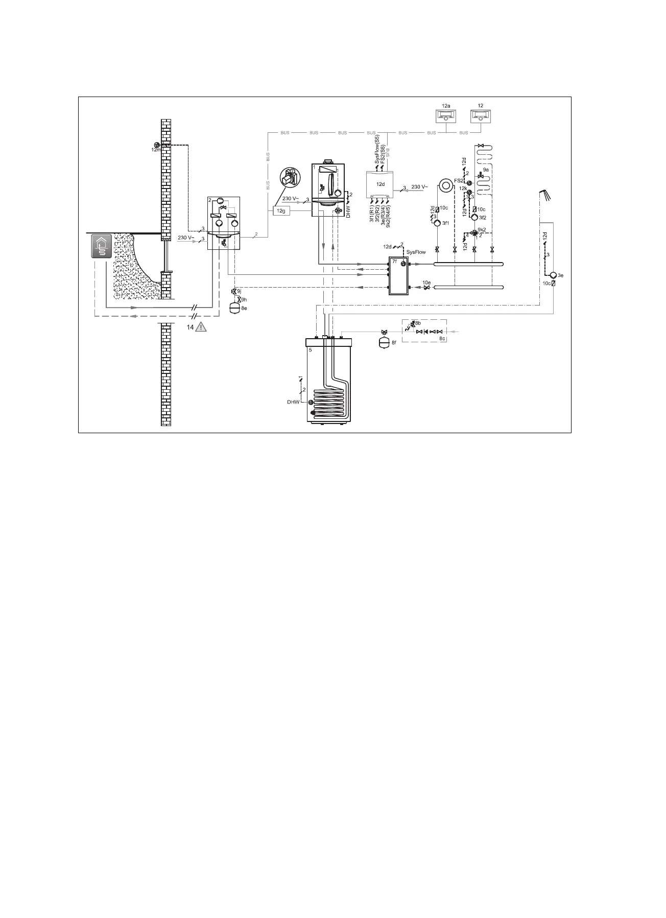
J.7 Basic hydraulic diagram 0020235626
1 Heat generator
2 Heat pump
3e Circulation pump
3f Heating pump
5 Monovalent domestic hot water cylinder
7f Decoupler module
8b Potable water expansion relief valve
8c Safety group – drinking water connection
8e Heating diaphragm expansion vessel
8f Diaphragm expansion vessel – potable water
9a Single-room temperature control valve (thermo-
static/motorised)
9h Filling/draining cock
9j Tamper-proof capped valve
9k 3-port mixing valve
10c Non-return valve
10e Line strainer with magnetite separator
12 System control
12a Remote control unit
12d Expansion/wiring centre
12g eBUS bus coupler
12k Limit thermostat
12m Outdoor temperature sensor
DHW Cylinder temperature sensor
FS Flow temperature sensor
SysFlow Cylinder temperature sensor

 Loading...


