Appendix
48 Installation and maintenance instructions geoTHERM 0020250180_00
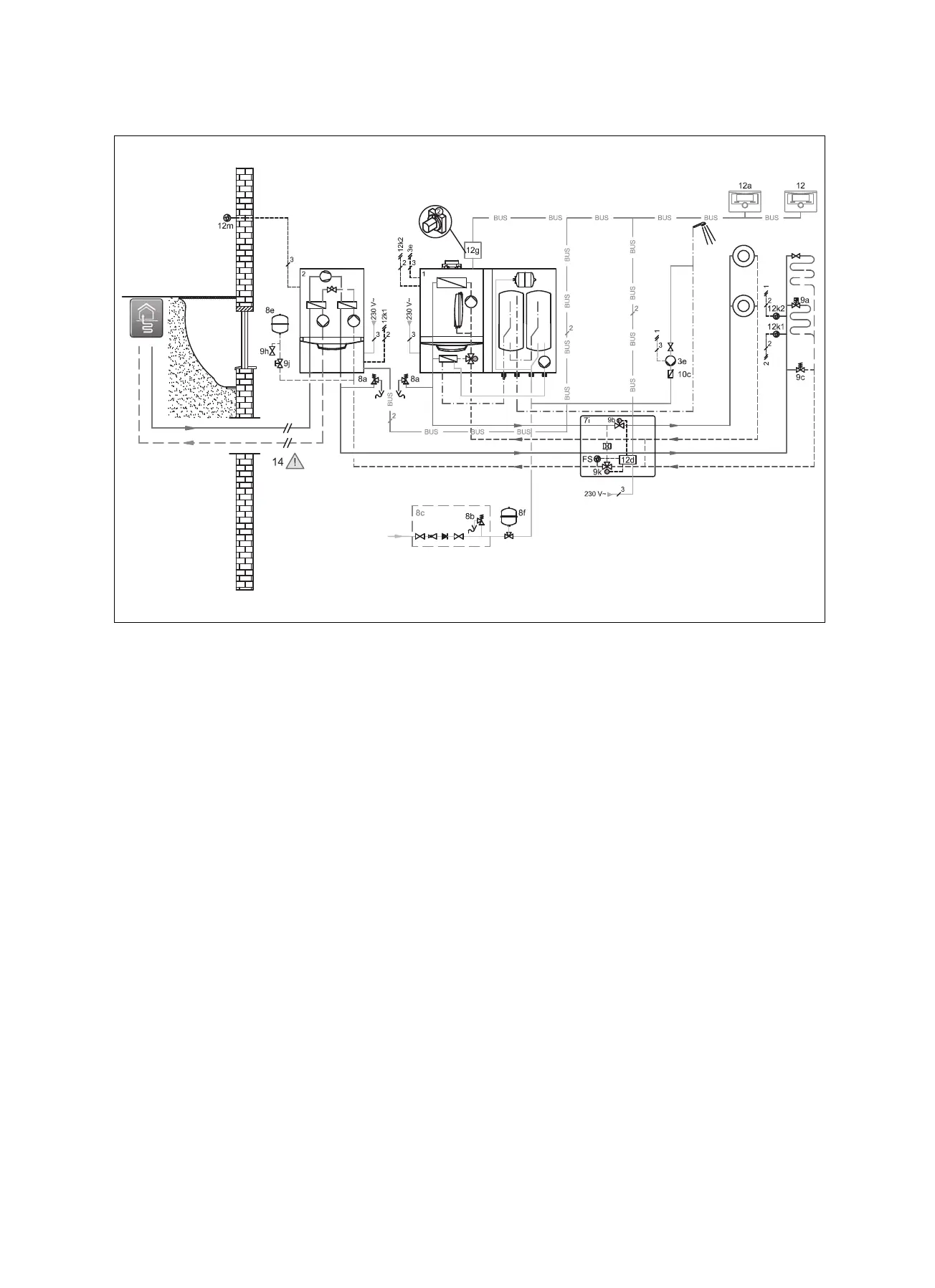
J.6 Basic hydraulic diagram 0020180635
1 Heat generator
2 Heat pump
3e Circulation pump
5 Monovalent domestic hot water cylinder
7i 2-zone module
8a Expansion relief valve
8b Potable water expansion relief valve
8c Safety group – drinking water connection
8e Heating diaphragm expansion vessel
8f Diaphragm expansion vessel – potable water
9a Single-room temperature control valve (thermo-
static/motorised)
9b Zone valve
9c Flow regulator valve
9d Bypass valve
9h Filling/draining cock
9j Tamper-proof capped valve
9k 3-port mixing valve
10c Non-return valve
12 System control
12a Remote control unit
12d Expansion/wiring centre
12g eBUS bus coupler
12k Limit thermostat
12m Outdoor temperature sensor
Using a 2-zone set and the appropriate information in the VRC 700 system control also makes the parallel heating mode
possible for parallel operation of different temperature levels in the heating system with the different heat generators.
For the parallel heating mode, the 2-zone kit (Vaillant accessory) must be installed. The heat pump, the gas-fired boiler and
the required heating circuits are connected to the 2-zone kit. When using a 2-zone kit (Vaillant accessory), the two non-return
flaps are not required.
– Connect two limit thermostats to guarantee the underfloor heating protection function for the heat pump and the gas-fired
boiler
– Ensure that a minimum circulation water volume (40% of the nominal volume flow) is guaranteed.
– Install the control in the living room.

 Loading...


