Operating and Installation Manual for uniSTOR, auroSTOR, geoSTOR Cylinders 0020080043_00 6
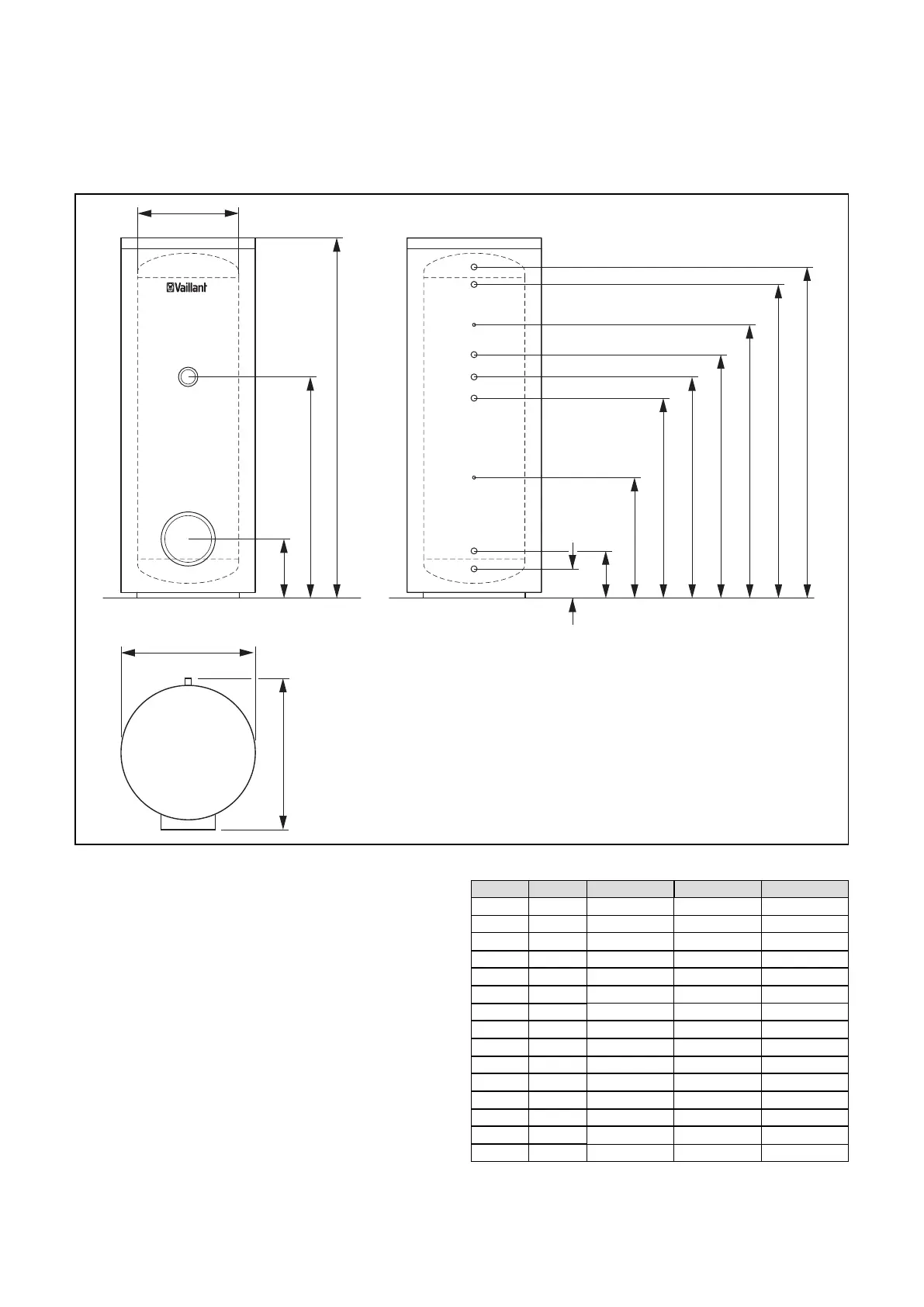
5.2.2 Unit and connection dimensions VIH S
Ø
b
D
B
M
L
K
J
I
H
G
F
E
t
C
A
3
4
5
6
7
8
9
10
11
1
2
Fig. 5.2 Unit and connection dimensions VIH S
Key to Fig. 5.2
1 Connection for heating element (G1 1/2)
2 Inspection opening (Ø120)
3 Hot water connection (R1)
4 Heating flow (R1)
5 Pocket for heating sensor (Ø12)
6 Heating return (R1)
7 Circulation connection (R3/4)
8 Solar flow (R1)
9 Pocket for solar sensor (Ø12)
10 Solar return (R1)
11 Cold water connection (R1)
Type Units VIH S 300 VIH S 400 VIH S 500
A mm 1775 1470 1775
B mm 279 308 308
C mm 1086 862.5 1062.5
D mm 500 650 650
E mm 1632 1301 1601
F mm 1546 1215 1515
G mm 1346 1065 1315
H mm 1196 965 1165
I mm 1086 862.5 1062.5
J mm 981 760 960
K mm 581 510 610
L mm 216 245 245
M mm 130 159 159
b mm 660 810 810
t mm 725 875 875
Table 5.1 VIH S unit dimensions
5 Installation
 Loading...