Installation and maintenance instructions for uniSTOR 0020111105_00 15
5 Installation
a
Danger!
Risk of injuries and damage
due to improper installation!
Improper installation can impede the opera-
tional safety of the unit.
> Only a competent person may install and
commission the unit.
This person takes responsibility for
making sure that the unit is installed and
commissioned for the first time correctly
and in accordance with regulations.
a
Danger!
Risk of burns from lines!
There is a risk of burns from system pipes
without thermal insulation. Energy losses
also occur in such cases.
> Provide all system pipes with thermal
insulation.
> Use screw connections to close all supply
lines.
b
Caution!
Risk of damage resulting from improper
use and/or unsuitable tools!
Improper use and/or unsuitable tools may
result in material damage (e.g. gas or water
leaks).
> Always use a suitable open-ended span-
ner to tighten or undo threaded connec-
tions.
> Do not use pipe wrenches, extensions,
etc.
b
Caution!
Risk of damage from leaks!
Mechanical stress on supply lines can result
in leaks and thus damage to the heat pump.
> Avoid mechanical stress on supply lines!
5.1 Installing pipes for the reheating circuit
> Make sure that the pipes in the reheating circuit between
the gas-fired wall-hung boiler and cylinder are as short
as possible. Use copper piping with a minimum diameter
of 22mm.
A heating pump is installed in all Vaillant gas-fired wall-
hung boilers (apart from the ecoTEC plus 400 with open
ventilation). If you are using the cylinder with another
gas-fired wall-hung boiler as per GB standards, you may
have to install a suitable heating pump in the reheating
circuit.
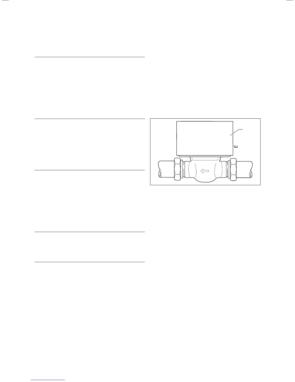
Installing the two port motorised valve
1
Fig. 5.1 Two port motorised valve
The two port motorised valve prevents the cylinder from
overheating.
> Install the two port motorised valve (1) supplied with the
cylinder in the flow line (A¬fig.3.1) of the gas-fired wall-
hung boiler.
> Note the direction of flow, which is marked with arrows.
i
The two port valve must only be installed hori-
zontally and with the valve head facing upwards
(¬ fig. 5.1).
Installation 5