18 Installation and maintenance instructions for uniSTOR 0020111105_00
5.3.4 Mounting the drain valve
> Mount a drain valve (10) (¬ fig. 3.2) as low as possible
between the cylinder and the safety assembly in the cold
mains inlet.
The drain valve must be provided by the customer.
We recommend mounting a hose which reaches about
1 m under the base of the cylinder to the outlet of the
drain valve.
5.3.5 Laying the pipes to the tundish
> Connect the temperature and pressure relief valve and
the expansion relief valve to the tundish using
15 mm piping.
> Lay the tundish discharge pipe (¬section 5.4).
i
The tundish discharge pipes must be laid at a
sufficient distance from electrical components in
accordance with valid building regulations.
5.4 Installation of discharge pipe
5.4.1 Design of discharge pipe
a
Danger!
Risk of burns and scalds resulting from
escaping hot water!
In the event of a fault, hot water can escape
suddenly from the discharge pipe of the
expansion relief valve.
> Lay the discharge pipe so that it ends at
an easily visible point inside or outside
the building where escaping hot water
does
not pose a risk to persons.
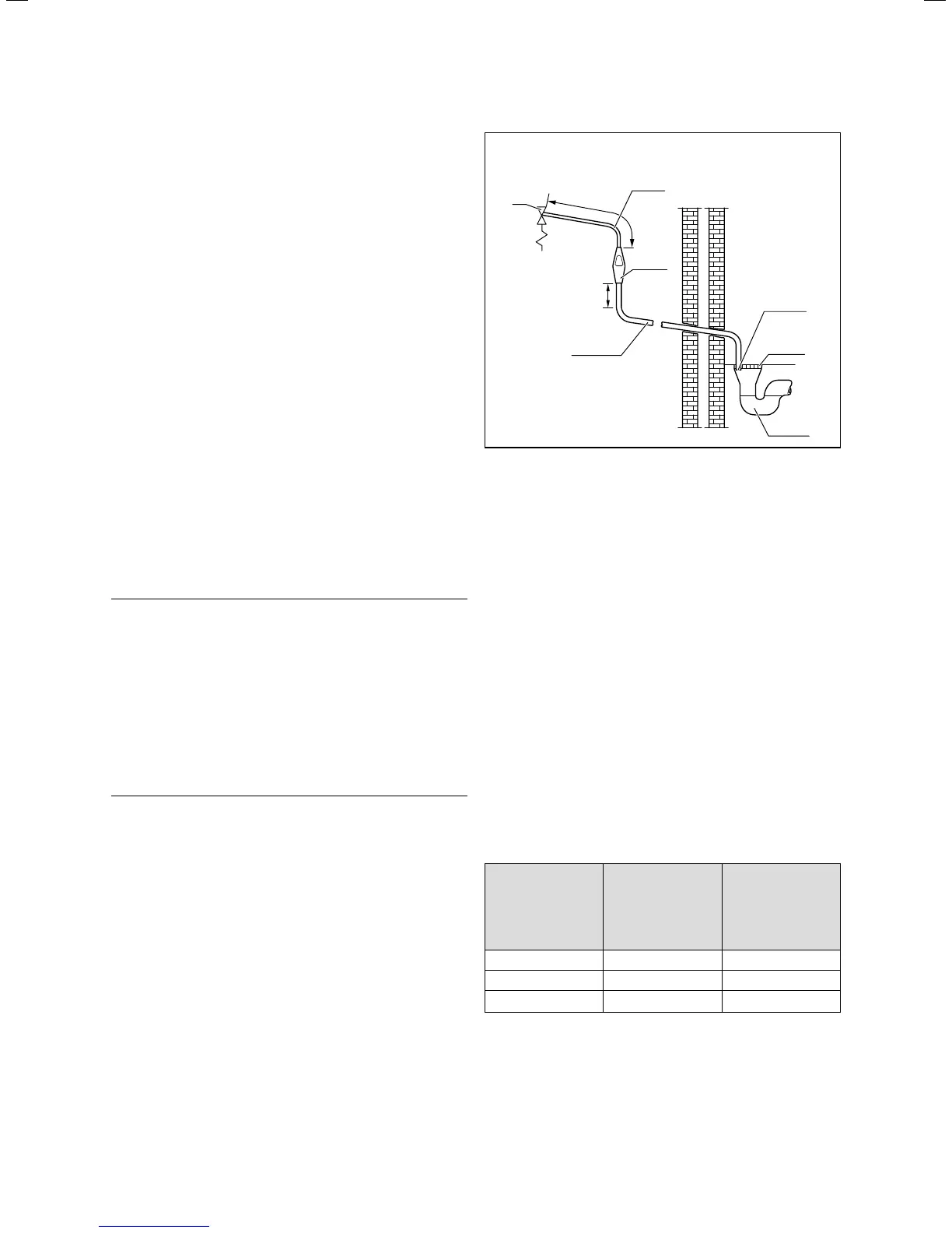
Metal discharge pipe (D1)
from temperature and pressure
relief valve to tundish
Metal discharge pipe (D2)
from tundish with constant
incline
Tundish
Discharge point
beneath grille
Fixed grille
Gully with
siphon
Safety valve
(e.g. Temperature
and pressure
relief valve)
At least
300 mm
Max.
600 mm
Fig. 5.5 Typical drainage installation
The discharge connections of the temperature and pres-
sure relief valve and the expansion relief valve must be
connected to the supplied tundish via 15 mm copper pip-
ing. The tundish should be mounted vertically, as close
to the cylinder as possible and not more than 600 mm
from the connection of the temperature and pressure
relief valve. It must be mounted in the same room as the
cylinder at a sufficient distance from the electrical com-
ponents. The discharge pipes from the temperature and
pressure relief valve and the expansion relief valve can
be joined above the tundish using a T-piece.
The discharge pipe from the 22 mm connection of the
tundish must be laid using copper piping with a diameter
of at least 22 mm to a safe and visible discharge point.
There must be a vertical section of pipe at least 300 mm
long beneath the tundish before any bends or elbows in
the pipework. If the total resistance of the discharge
pipe exceeds the values specified in Tab. 5.1 below, you
must increase the diameter of the piping. When install-
ing the discharge piping, you must observe Directive G3
(¬section 2.2).
Minimum diameter
of discharge pipe
(D2) from tundish
Maximum permis-
sible total resist-
ance, expressed
as straight pipe
length (without
elbows or bends)
Resistance due to
each elbow or bend
22 mm up to 9 m 0.8 m
28 mm up to 18 m 1.0 m
35 mm up to 27 m 1.4 m
Tab. 5.1 Sizing of copper discharge pipe “D2” for G1/2 tempera-
ture and pressure relief valve outlet size
5 Installation