24 Installation and maintenance instructions for uniSTOR 0020111105_00
5.5.4 Installing the control components in accordance
with the connection wiring diagrams
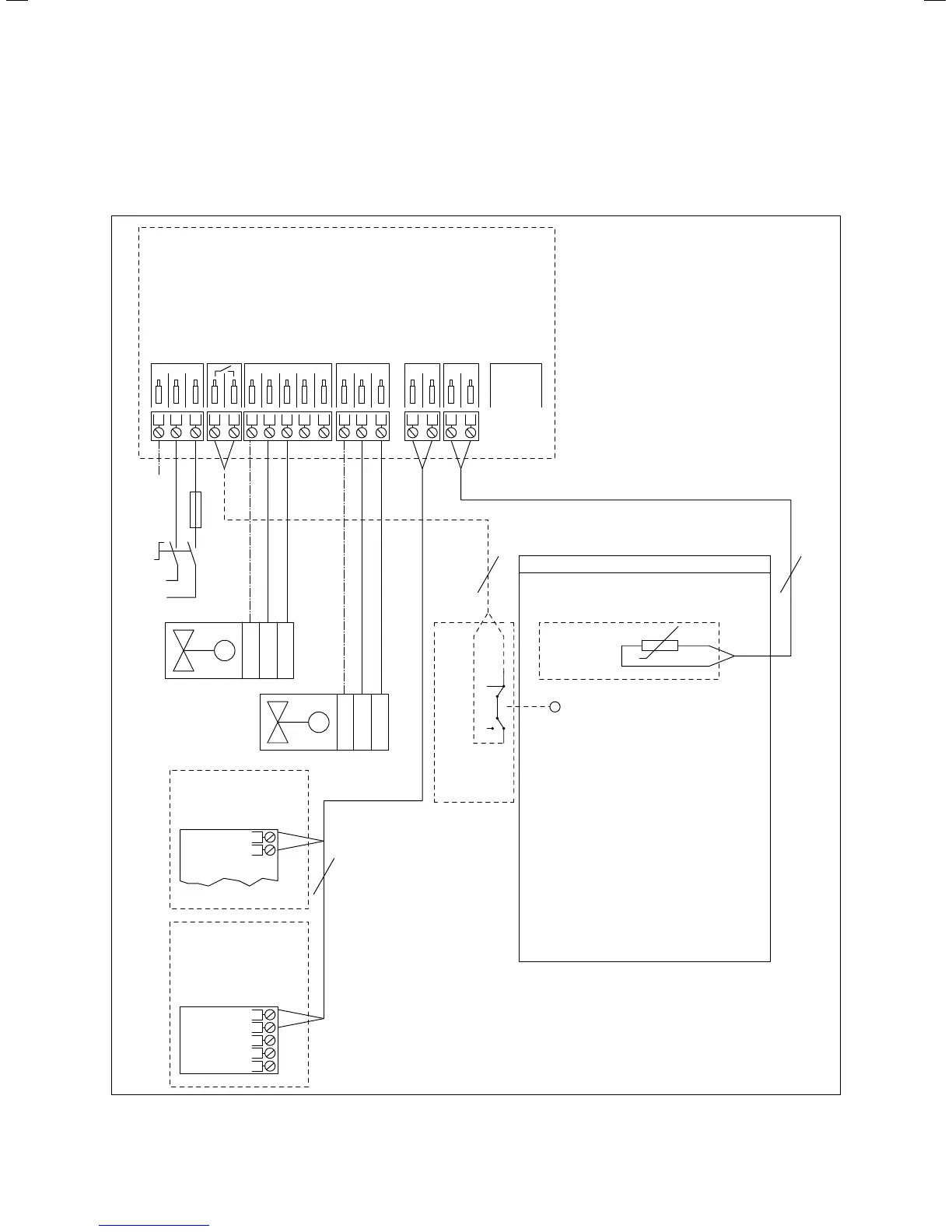
Connection wiring diagram 1 (S plan)
C
21
230 V grid
VR 65
CH
DHW
BUS
DHW
NTC
CYL.
21+-NPE onNPE L offonNPE on
DO NOT
USE
M
PE
Blue
Brown
DHW
M
PE
Blue
Brown
CH
Cylinder thermostat
and TCO
22
NTC
BUS
Vaillant
ecoTEC
+
-
BUS
Vaillant
dual-channel
eBUS controller
+
-
2
PE 3A
N
L
Cylinder
Fig. 5.10 Connection wiring diagram 1
5 Installation

 Loading...