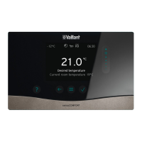
7 Operating and display functions
22 Installation instructions 0020237057_01
– You can use this function to read the current measured
value for the bottom cylinder temperature sensor.
7.13 2nd differential temperature control
7.13.1 Defining the switch-on differential for the
second differential temperature control
Menu → Installer level → System configuration → [2nd
temperature difference control ----] → Switch-on diff.
– You can use this function to define a differential value for
starting the differential temperature control, such as solar
heating support.
If the difference between differential temperature sensor 1
and differential temperature sensor 2 exceeds the specified
switch-on differential and the minimum temperature at differ-
ential temperature sensor 1, the system control then controls
the differential temperature output. The differential temperat-
ure control starts.
7.13.2 Defining the switch-off differential for the
second differential temperature control
Menu → Installer level → System configuration → [2nd
temperature difference control ----] → Switch-off diff.
– You can use this function to define a differential value
for stopping the differential temperature control, such as
solar heating support.
If the difference between differential temperature sensor 1
and differential temperature sensor 2 falls below the spe-
cified switch-off differential or exceeds the maximum temper-
ature at differential temperature sensor 2, the system control
then controls the differential temperature output. The differ-
ential temperature control stops.
7.13.3 Setting the minimum temperature
Menu → Installer level → System configuration → [2nd
temperature difference control ----] → Minimum temper-
ature
– You can use this function to set the minimum temperat-
ure in order to start the temperature difference control.
Defining the switch-on differential for the second temperature
difference control (→ Page 22)
7.13.4 Setting the maximum temperature
Menu → Installer level → System configuration → [2nd
temperature difference control ----] → Maximum temper-
ature
– You can use this function to set the maximum temperat-
ure in order to stop the temperature difference control.
Defining the switch-off differential for the second temperature
difference control (→ Page 22)
7.13.5 Reading the value for temperature
difference sensor 1
Menu → Installer level → System configuration → [2nd
temperature difference control ----] → TD1 sensor
– You can use this function to read the current measured
value for temperature difference sensor 1 (TD1).
7.13.6 Reading the value for temperature
difference sensor 2
Menu → Installer level → System configuration → [2nd
temperature difference control ----] → TD2 sensor
– You can use this function to read the current measured
value for temperature difference sensor 2 (TD2).
7.13.7 Reading the status of the temperature
difference control
Menu → Installer level → System configuration → [2nd
temperature difference control ----] → TD output
– You can use this function to read the status of the tem-
perature difference control.
7.14 Ventilation
7.14.1 Reading the air quality sensor
Menu → Installer level → System configuration → [Ventila-
tion ----] → Air quality sensor 1/2
– You can use this function to read the measured values
from the air quality sensor.
7.14.2 Setting the maximum value for air quality
sensor
Menu → Installer level → System configuration → [Ventila-
tion ----] → Max. air qual. sensor
– You can use this function to set a maximum value for the
air quality.
If the air quality exceeds the maximum value specified, the
system control activates the recoVAIR.../4 ventilation unit
accordingly. You will find a detailed functional description in
the recoVAIR.../4 manual.
7.15 Radio link
7.15.1 Reading the reception strength for the
system control
Menu → Installer level → System configuration → [RF con-
nection ----] → Control reception
– You can use this function to read how strong the recep-
tion strength between the radio receiver unit and the sys-
tem control is.
4: The radio link is within the acceptable range. If the recep-
tion strength is < 4, the radio link is not stable.
10: The radio link is highly stable.
7.15.2 Reading the reception strength for the
outdoor temperature sensor
Menu → Installer level → System configuration → [RF con-
nection ----] → OT sensor reception
– You can use this function to read how strong the recep-
tion strength between the radio receiver unit and the out-
door temperature sensor is.
4: The radio link is within the acceptable range. If the recep-
tion strength is < 4, the radio link is not stable.
10: The radio link is highly stable.
 Loading...