Appendix
0020237057_01 Installation instructions 37
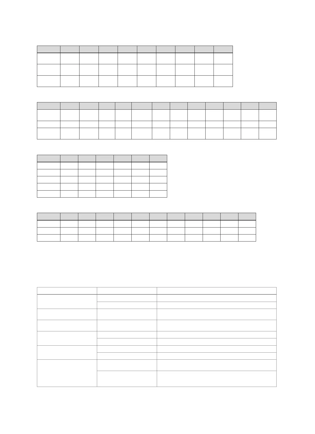
C.3 Connecting the actuators to VR 71
Set value R1 R2 R3 R4 R5 R6 R7/R8 R9/R10 R11/R12
2 3f1 3f2 3f3 MA COLP1 LP/9e 9k1op/
9k1cl
9k2op/
9k2cl
9k3op/
9k3cl
3 3f1 3f2 3f3 MA LP/9e 9k1op/
9k1cl
9k2op/
9k2cl
9k3op/
9k3cl
6 3f1 3f2 3f3 MA LP/9e 9k1op/
9k1cl
9k2op/
9k2cl
9k3op/
9k3cl
C.4 Connecting the sensors to VR 71
Set value S1 S2 S3 S4 S5 S6 S7 S8 S9 S10 S11 S12
2 SysFlow FS2 FS3 FS4 DHWTop DHWBt COL1 Solar
Yield
eyield TD1 TD2 PWM1
3 SysFlow FS2 FS3 FS4 BufBt DEM2 DEM3 DEM4 DHW1
6 SysFlow FS2 FS3 FS4 BufTop
HC
BufBt
HC
BufTop
DHW
BufBt
DHW
DEM2 DEM3 DEM4
C.5 VR 70 sensor assignment
Set value S1 S2 S3 S4 S5 S6
1 VR 10 VR 10 VR 10
3 VR 10 VR 10 VR 10 VR 10 VR 10 VR 10
5 VR 10 VR 10 VR 10
6 VR 10 VR 10 VR 10 VR 11 VR 10
12 VR 10 VR 10 VR 10 VR 10 VR 11 VR 10
C.6 VR 71 sensor assignment
Set value S1 S2 S3 S4 S5 S6 S7 S8 S9 S10 S11
2 VR 10 VR 10 VR 10 VR 10 VR 10 VR 10 VR 11 VR 10 VR 10 VR 10 VR 10
3 VR 10 VR 10 VR 10 VR 10 VR 10 VR 10
6 VR 10 VR 10 VR 10 VR 10 VR 10 VR 10 VR 10 VR 10
D Overview of troubleshooting measures
D.1 Troubleshooting
In column 1 in the table, a $ symbol is displayed after the sensor. The $ symbol is a placeholder for the sensor number. The
% symbol after various components is a placeholder for the address of the component. In both cases, on the display, the
system control replaces the symbol with the specific sensor or specific address.
Message Possible cause Measure
Additional module fault The cable is defective ▶ Replace the cable.
Incorrect plug connection ▶ Check the plug connection.
Cascades not supported Incorrectly selected system dia-
gram
▶ Set the correct system diagram that contains cascades.
Combination of VR70 and
VR71 not permitted
VR 70 and VR 71 are connec-
ted in combination
▶ Connect either the VR 70 or the VR 71.
Communication fault: Heat
generator %
The cable is defective ▶ Replace the cable.
Incorrect plug connection ▶ Check the plug connection.
Communication fault: Heat
pump %
The cable is defective ▶ Replace the cable.
Incorrect plug connection ▶ Check the plug connection.
Communication fault: VR91 % The batteries in the remote con-
trol are flat
▶ Change all the batteries (→ Operating and installation instruc-
tions for the VR 91f).
The batteries in the remote con-
trol have not been inserted cor-
rectly
▶ Insert the batteries in the battery compartment, making sure
that the poles are the right way round (→ Operating and install-
ation instructions for the VR 91f).
 Loading...