Appendix
38 Installation instructions 0020237057_01
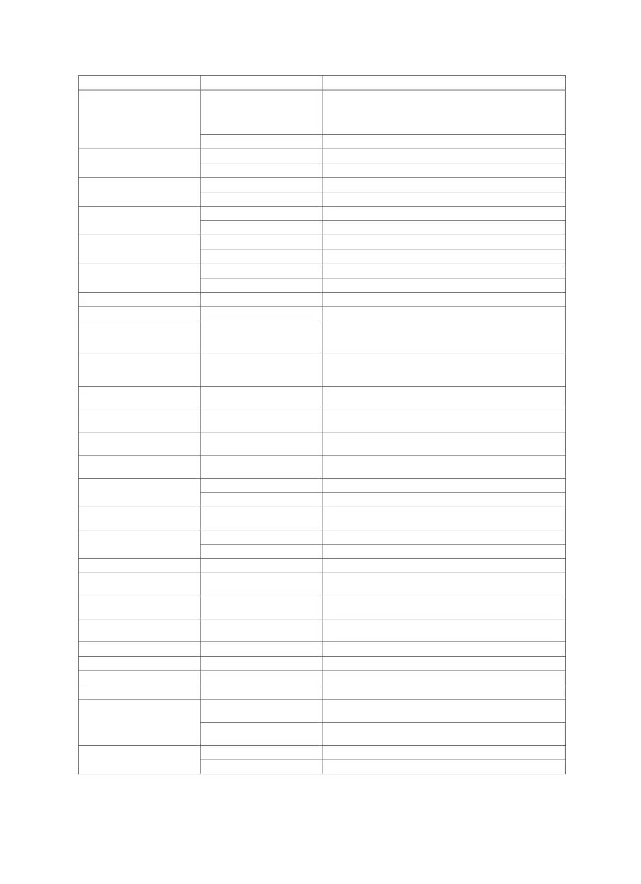
Message Possible cause Measure
Communication fault: VR91 % The remote control is outside
the radio reception range
1. Take the remote control to the radio receiver unit and see if
the reception strength increases.
2. If the reception strength is ≤ 4, find a new installation site for
the remote control.
The remote control is defective ▶ Replace the remote control unit.
Communication fault: VMS The cable is defective ▶ Replace the cable.
Incorrect plug connection ▶ Check the plug connection.
Communication fault: VPM-S The cable is defective ▶ Replace the cable.
Incorrect plug connection ▶ Check the plug connection.
Communication fault: VPM-W The cable is defective ▶ Replace the cable.
Incorrect plug connection ▶ Check the plug connection.
Communication fault: VR70 % The cable is defective ▶ Replace the cable.
Incorrect plug connection ▶ Check the plug connection.
Communication fault: VR71 The cable is defective ▶ Replace the cable.
Incorrect plug connection ▶ Check the plug connection.
Fault: Heat generator % Fault in the heat generator ▶ See the instructions for the heat generator displayed.
Fault: Heat pump % Fault in the heat pump ▶ See the instructions for the heat pump displayed.
Incorrect configuration: VR70
% MA
Incorrectly selected setting
value for the multi-function
output
▶ In the MA VR70, addr. 1 function, set the setting value that is
appropriate for the connected component on the VR 70's multi-
function output.
Incorrect configuration: VR71 Incorrectly selected setting
value for the multi-function
output
▶ In the MA VR71 function, set the setting value that is appropri-
ate for the connected component on the VR 71's multi-function
output.
Incorrect configuration: VR70 Incorrect set value for the
VR 70
▶ Set the correct set value for the VR 70.
Incorrect configuration: VR71 Incorrect setting value for the
VR 71
▶ Set the correct setting value for the VR 71.
System diagram selection
incorrect
Incorrectly selected system dia-
gram
▶ Set the correct system diagram.
Module not supported Unsuitable module connected,
e.g.VR 61, VR 81
▶ Install a module that the system control supports.
No additional module connec-
tion
The cable is defective ▶ Replace the cable.
Incorrect plug connection ▶ Check the plug connection.
No remote control for heating
circuit %
No remote control unit ▶ Connect the remote control unit.
Ventilation unit connection The cable is defective ▶ Replace the cable.
Incorrect plug connection ▶ Check the plug connection.
No VR70 for this system Missing VR 70 ▶ Connect the VR 70.
Hot water temperature sensor
S1 not connected
Hot water temperature sensor
S1 not connected
▶ Connect the hot water temperature sensor to the VR 70.
Outside temperature sensor
damaged
Outside temperature sensor
faulty
▶ Replace the outside temperature sensor.
Room temp. sensor fault The room temperature sensor is
defective
▶ Replace the remote control unit.
Sensor fault S $ VR70 % Sensor defective ▶ Replace the sensor.
Sensor fault S $ VR71 Sensor defective ▶ Replace the sensor.
Fault: Solar pump % Fault in the solar pump ▶ Check the solar pump.
Ventilation unit fault Ventilation unit fault ▶ See the instructions for recoVAIR.../4 and later models.
VR71 not supported for this
system
VR 71 connected in the heating
installation
▶ Remove the VR 71 from the heating installation.
Incorrectly selected system dia-
gram
▶ Set the correct system diagram.
Incorrect configuration: MA2
VWZ-AI
Incorrectly connected VR 70 ▶ Connect the VR 70 to the appropriate basic system diagram.
Incorrectly connected VR 71 ▶ Connect the VR 71 to the appropriate basic system diagram.
 Loading...