Appendix
0020237057_01 Installation instructions 31
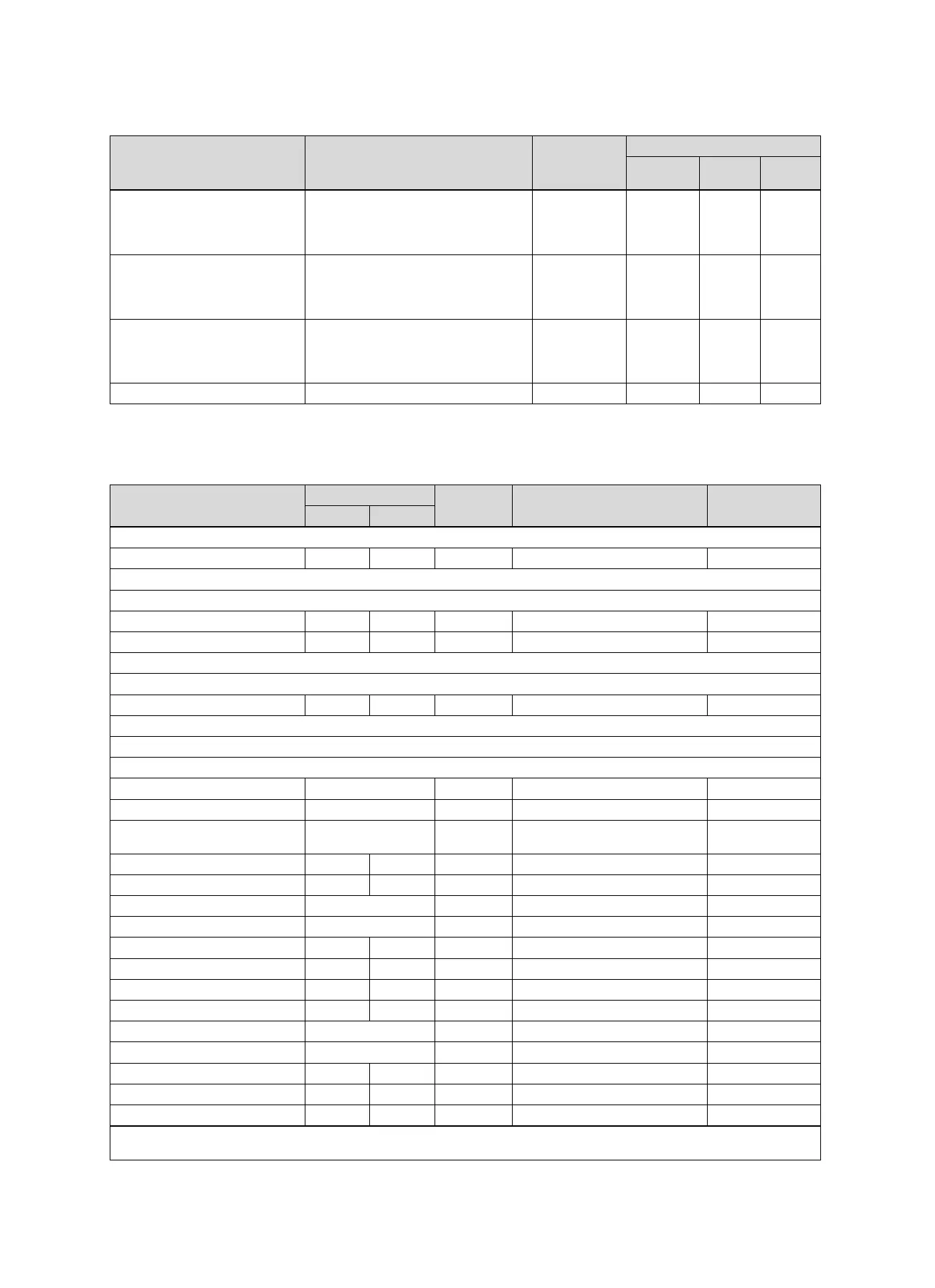
A.17 aroTHERM and gas-fired condensing boiler (eBUS), heat pump cascade option
Cylinder Equipment Heating cir-
cuits
Setting for
System
diagram
VR 70 VR 71
Buffer cylinder Domestic hot water cylinder downstream
of low loss header/buffer cylinder
Buffer cylinder charging using the system
controller
1 direct
1 mixed
16 1
allSTOR buffer cylinder Domestic hot water cylinder downstream
of low loss header/buffer cylinder
Buffer cylinder charging using the system
controller
1 direct
1 mixed
16 3
Buffer cylinder Domestic hot water cylinder downstream
of low loss header/buffer cylinder
Buffer cylinder charging using the system
controller
3 mixed 16 3
allSTOR buffer cylinder 3 mixed 16 6
B Overview of the setting options
B.1 Installer level
Setting level Values Unit Increment, select Default setting
Min. Max.
Installer level →
Enter code 000 999 1 000
Installer level → Service information → Enter contact details →
Phone number 1 12 Numbers 0 to 9, blank spaces, hyphen
Installer 1 12 Figures A to Z, 0 to 9, space
Installer level → Service information → Service date →
Next service on Date
Installer level → System configuration →
System ----
Fault status Current value*
Water pressure Current value bar
System status Current value Standby, Heat. mode, Cooling,
DHW
Frost protect. delay 0 12 h 1 4
OT constant heating off, -25 10 ℃ 1 off
Control modules Display Software version
Adaptive heat. curve Current value Yes, No No
Configure heat. circ. All, Zone Zone
Automatic cooling Yes, No No
Start OT cooling 10 30 ℃ 1 21
Source regeneration Yes, No No
Current room air hum. Current value %
Current dew point Current value ℃
Hybrid manager triVAI, Biv. point Biv. point
Heat. bivalence point -30 20 ℃ 1 0
DHW bivalence point -20 20 ℃ 1 -7
* If no fault is present, the status is No fault. If there is a fault, Fault list appears and you can read the fault message in the "Fault mes-
sages" section.
 Loading...