Notes on the documentation 2
0020237057_01 Installation instructions 5
2 Notes on the documentation
2.1 Observing other applicable documents
▶ You must observe all the operating and installation in-
structions included with the system components.
2.2 Storing documents
▶ Pass these instructions and all other applicable docu-
ments on to the system operator.
2.3 Validity of the instructions
These instructions apply only to:
VRC 700f/4 – article number
Great Britain
0020231564
2.4 Nomenclature
The following terms are used for simplification:
– Heat pump: This refers to all heat pumps
– Hybrid heat pump: This refers to the VWS 36/4 230 V
and VWL 35/4 S 230 V hybrid heat pumps.
– System control: This refers to the VRC 700f radio control.
– Remote control: This refers to the VR 91 wireless remote
control.
– Outdoor temperature sensor: This refers to the VR 20
and VR 21 wireless outdoor temperature sensors.
3 Product description
3.1 Data plate
The data plate is located on the rear of the system control
underneath the unit mounting bracket.
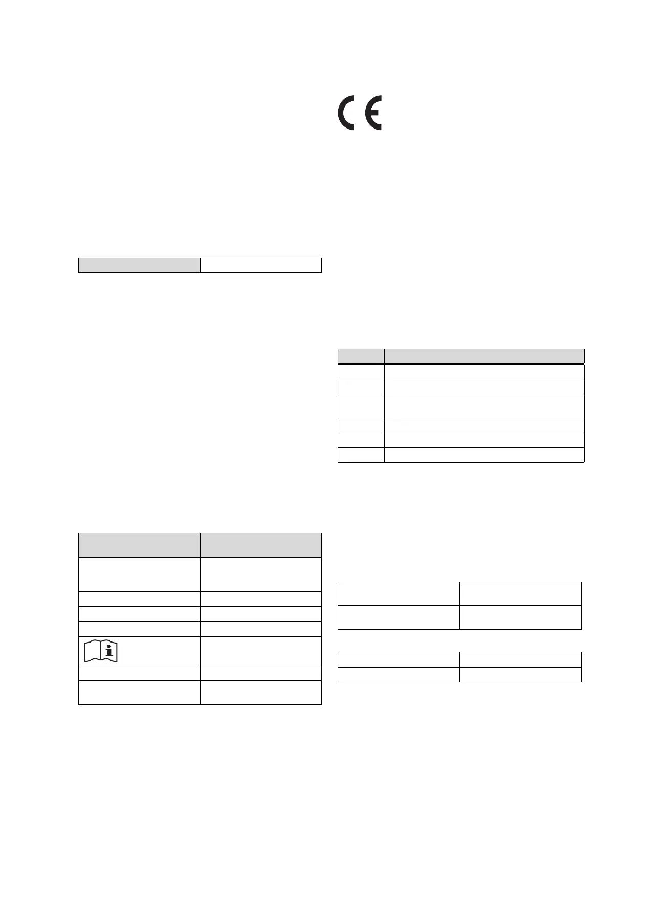
The data plate contains the following information:
Information on the identific-
ation plate
Meaning
Serial number for identification; 7th to
16th digits = product article
number
VRC 700f/4 Product designation
V Operating voltage
mA Current consumption
Read the instructions
LR06 Battery type designation
T60 Max. permitted environmental
temperature: 0 to 60 °C
3.2 CE marking
The CE mark shows that the products comply with the basic
requirements of the applicable guidelines as stated on the
data plate.
The manufacturer hereby declares that the type of radio
equipment that is described in these instructions complies
with Directive 2014/53/EU. The complete text for the EU De-
claration of Conformity is available at: http://www.vaillant-
group.com/doc/doc-radio-equipment-directive/.
4 Set-up
Obstacles weaken the reception strength between the radio
receiver unit and the system control or outdoor temperature
sensor.
4.1 Checking the scope of delivery
Quantity Contents
1 System control
1 Radio receiver unit with wall base
1 VR 20 outdoor temperature sensor or VR 21 out-
door temperature sensor
1 Fastening material (2 bolts and 2 wall plugs)
4 Batteries, LR06
1 Documentation
▶ Check that the scope of delivery is complete.
4.2 Selecting the lines
▶ Use standard commercial lines for the wiring.
▶ Do not use flexible lines for mains voltage supply lines.
▶ Use insulation cables for mains voltage supply lines (e.g.
NYM 3 x 1.5).
Line cross-section
eBUS line (extra-low
voltage)
≥ 0.75 mm²
Sensor line (extra-low
voltage)
≥ 0.75 mm²
Line length
Sensor lines
≤ 50 m
Bus lines
≤ 125 m
 Loading...