Appendix
34 Installation instructions 0020237057_01
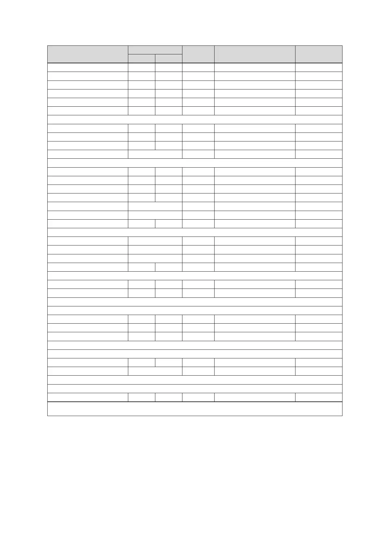
Setting level Values Unit Increment, select Default setting
Min. Max.
Solar flow volume 0.0 165.0 l/min 0.1
Solar pump boost off, On off
Solar circuit prot. 110 150 ℃ 1 130
Min. collector temp 0 99 ℃ 1 20
Purging time 0 600 min 10
Current flow rate 0.0 165.0 l/min 0.1
Solar cylinder 1 ----
Switch-on diff. 2 25 K 1 12
Switch-off diff. 1 20 K 1 5
Maximum temperature 0 99 ℃ 1 75
Cyl. temp.: Bottom Current value ℃
2nd temperature difference control ----
Switch-on diff. 1 20 K 1 5
Switch-off diff. 1 20 K 1 5
Minimum temperature 0 99 ℃ 1 0
Maximum temperature 0 99 ℃ 1 99
TD1 sensor Current value ℃
TD2 sensor Current value ℃
TD output off, On off
Ventilation ----
Air quality sensor 1 Current value ppm
Air quality sensor 2 Current value ppm
Air quality sensor 3 Current value ppm
Max. air qual. sensor 400 3000 ppm 100 1000
RF connection ----
Control reception 0 10 1
OT sensor reception 0 10 1
Installer level → Sensor/actuator test →
Unit No module, VR70 ad.1, VR71
Actuator No actuat., R1, to R12
Sensor No sensor, S1, to S13
Installer level → HEATING1 → Screed-drying function →
Day 00 29 Day 1 00
Temperature Current value ℃ 1
Installer level → Change code →
New code 000 999 1 00
* If no fault is present, the status is No fault. If there is a fault, Fault list appears and you can read the fault message in the "Fault mes-
sages" section.
 Loading...