User's Guide ________________________________________________________
14 _____________________________________________________ M210375en-A
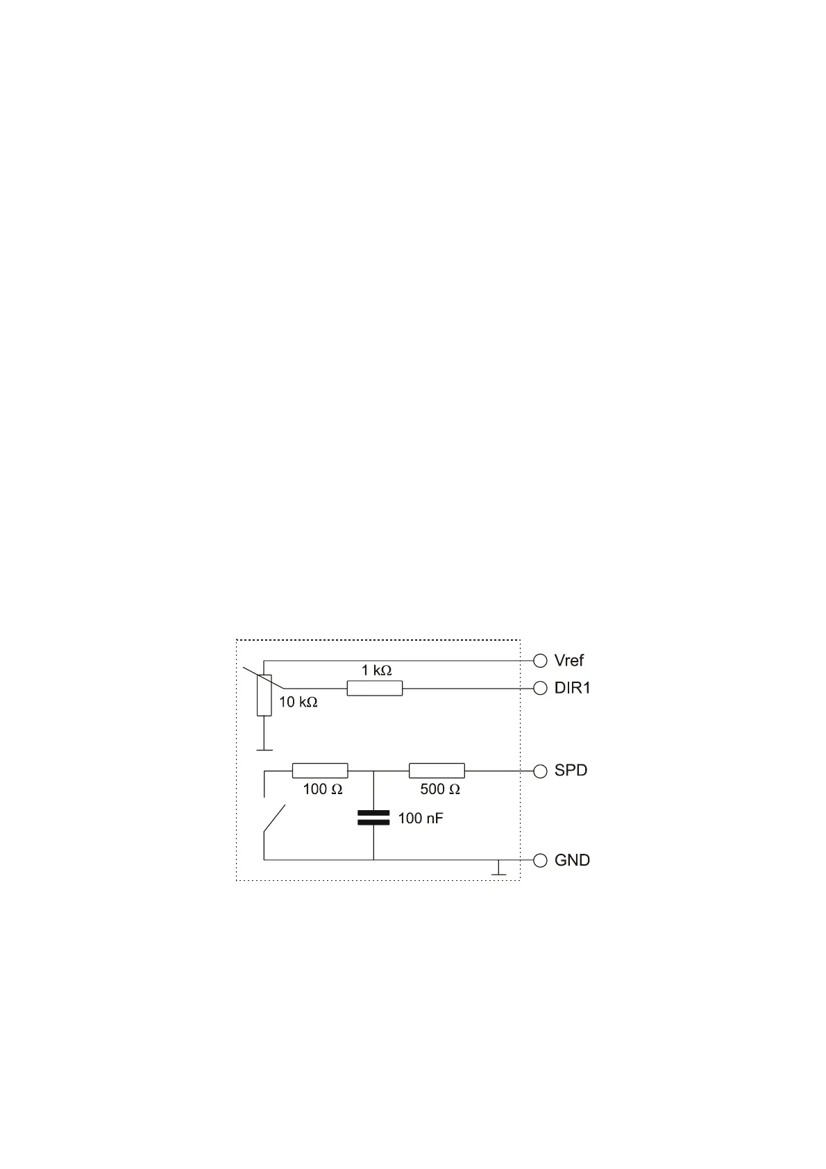
A pull up resistor, for example, 10 kΩ, is needed at SPD
output to supply the anemometer electronics. It is
recommended to use a Schmitt-trigger input with the SPD
signal.
Installation Procedure
Initial Check
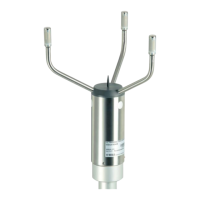
After you have unpacked the sensor, check for any signs of
shipping damage. Also test that the vane and cup wheel
rotate without friction.
Before installation, use an ohmmeter to check the proper
operation of speed (SPD) and direction (DIR1 and DIR2)
outputs while rotating the cup wheel and vane slowly. For
measuring the direction, note that 10 kΩ/360º and
10 kΩ/180° potentiometers are used with WMS301 and
WMS302 respectively. For the principal circuit diagrams,
refer to Figure 6 below and Figure 7 on page 15.
0212-224
Figure 6 WMS301 Principal Circuit Diagram