510
Thermo plus 160/230/300/350 5 Troubleshooting
5.6 Individual component tests
Individual components can basically be tested using
visual inspection or manual electrical testing.
In addition, the electrical components burner motor, circu-
lating pump, electronic ignition unit, solenoid valve, nozzle
block preheater, operation indicator and flame indicator
can be checked using the "Component Test" menu of the
STT diagnosis.
The check of the flameguard and the fuel pump pressure
is supported by the STT diagnosis.
5.6.1 General visual inspection
• Inspect components for damages (cracks, deforma-
tion, leaks, discolourations, etc.) and replace as
needed.
• Inspect plugs and cables for corrosion, contact and
crimp errors and repair as needed.
• Check plug contacts for corrosion and tight fit. Repair
as needed
5.6.2 Heat exchanger visual inspection
• Inspect heat exchanger interior for damage, corro-
sion, sooting and deposits.
• Inspect heat exchanger for outer damage, corrosion,
moisture, deformations, deposits, discolourations,
etc.
ATTENTION:
Soot and deposits in the heat exchanger must be re-
moved, as they impact the heat transfer to the coo-
lant.
Severe outer deformations may impact coolant flow.
5.6.2.1 Visual inspection of exhaust outlet and
exhaust line
Inspect exhaust outlet and possibly available exhaust line
for conditions, tight fit, contamination and deposits.
ATTENTION:
The exhaust gas temperature can reach over 400°C
depending on the heating capacity class.
– The exhaust pipe must end in the open air.
– The exhaust pipe must be sloped down, arising
condensate must be able to drain away.
– Because of the temperatures involved, sufficient
distance from heat-sensitive or flammable materi-
als must be ensured.
– Outflowing exhaust gas must not be re-sucked in
as combustion air.
– The opening of the exhaust pipe must be aligned
against the direction of travel and must not
become clogged with dirt or snow.
– If the exhaust outlet is under the vehicle floor,
blowing straight down, an exhaust gas deflection
is absolutely necessary.
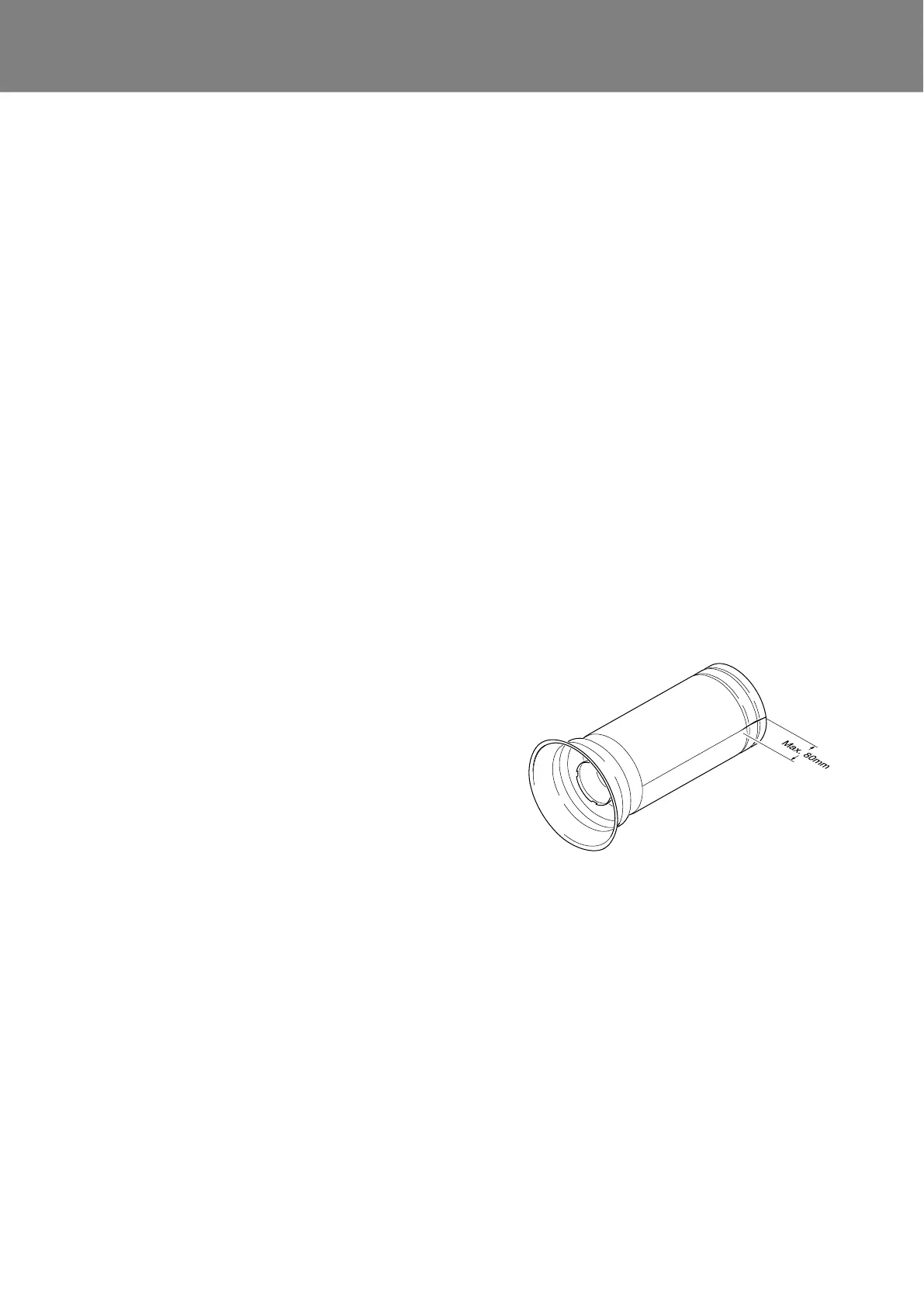
5.6.3 Combustion chamber visual inspection
• Remove combustion chamber (see 8.12).
• Inspect swirl plate and combustion chamber head for
damage and tight fit.
• Check and remove combustion chamber for scalings
and coke deposits as needed.
• Inspect combustion chamber for deformation and
moisture.
• Inspect welding seam and combustion chamber for
cracks.
NOTE:
Cracks in longitudinal direction at the end of the welding
seam shorter than 80 mm are permissible.
• After the inspection is completed, reinstall the com-
bustion chamber (siehe 8.12).
Fig. 501 Combustion chamber