514
Thermo plus 160/230/300/350 5 Troubleshooting
5.6.8 Ignition electrode inspection
NOTE:
The ignition electrode insulation may not be damaged.
Ignition electrodes not functioning properly must be
replaced.
ATTENTION:
Do not damage the electronic ignition unit when re-
moving the ignition electrode.
High voltage: The voltage received by the ignition
electrode is >13,000 Volt.
During operation or testing of the electronic ignition
unit, the ignition electrode may not be contacted by
persons or items.
Inspection
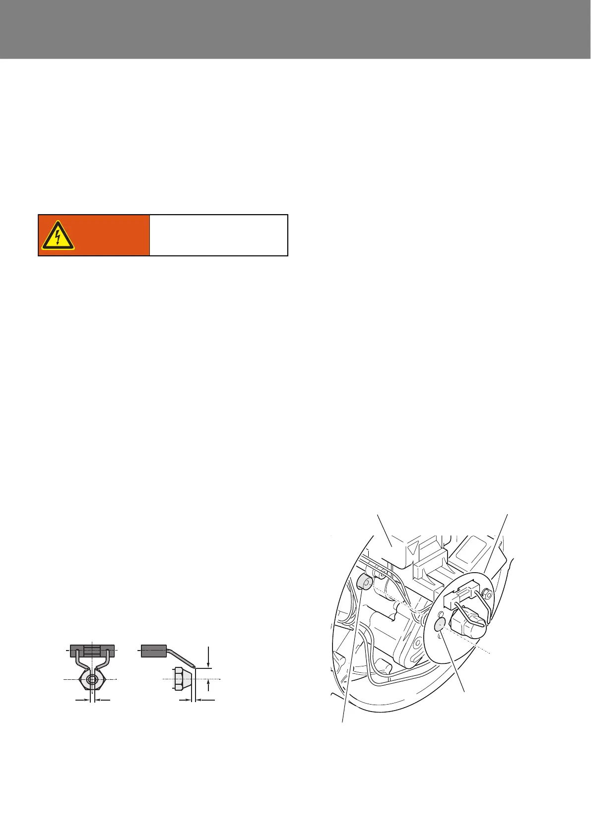
• Remove burner head (see 8.2).
• Check distance of the electrode tip to the atomizer
nozzle (see Fig. 508).
• Check the distance between the electrodes
(see Fig. 508).
NOTE:
Gauge 310646Z can be used to check and adjust the igni-
tion electrodes.
• If needed, lift off ignition electrode (3, Fig. 805) from
the electronic ignition unit by twisting a screwdriver
sideways (see Fig. 804).
• Inspect the ignition electrode insulation for damage.
• Functionality is verified while inspecting the electronic
ignition unit.
5.6.9 Flameguard inspection
NOTE:
In case of contamination the flameguard lens and the
inspection glass in the disc (see Fig. 509) must be
cleaned.
The flameguard is permanently integrated into the control
device and cannot be replaced.
Functionality is verified using STT diagnosis.
In case of damage or if the target value cannot be
reached, the control device must be replaced as needed.
Inspection
• Remove burner head (see 8.2).
• Reconnect the heater with the vehicle electrical
system.
• Connect the STT diagnosis to the heater.
• Start the STT diagnosis and establish connection to
the heater.
• Cover the flameguard lens.
• Check the flameguard voltage displayed on a PC by
the STT diagnosis (target value: U = 2.6V...3.3V).
• Remove the cover from the flameguard lens and illu-
minate it from close distance using a bright lamp.
• Check the flameguard voltage displayed on a PC by
the STT diagnosis (target value: U = 0.5V...1.6V).
• After the test is completed, exit STT diagnosis as
needed.
• Disconnect the heater from the vehicle electrical
system.
• Install burner head (see 8.2).
Fig. 508
Risc of electric shock!
Warning!
Fig. 509
Flameguard
Sight window
Electronic ignition unit
Disc
 Loading...