802
Thermo plus 160/230/300/350 8 Repairs
8.2 Burner head removal and installation
Burner head removal
1. Disconnect the heater from the vehicle electrical
system (Observe 5.2 !).
2. Disconnect the plug for the power supply/control (C).
3. Disconnect the plug for the circulating pump (P).
4. Disconnect the temperature sensor plug (T).
5. If necessary, disconnect the combustion air intake line
from the heater.
NOTE:
Make sure that any fuel leaking during the following work
step is immediately bound and professionally disposed of.
6. Unscrew fuel lines (4, Fig. 801) and seal with blank
plugs.
7. Unscrew nuts (2).
8. Remove burner head (1).
NOTE:
Do not bent any lines when placing the burner down.
Burner head installation
1. Bring burner head (1, Fig. 801) in assembly position
and ensure center alignment and correct fit.
2. Place nuts (2) and alternately tighten them slightly.
3. Tighten nuts (2) with 7.5 Nm + 1 Nm.
4. If applicable, bolt fuel lines down with 16 ± 1 Nm using
a banjo bolt and new gaskets, or slide on fuel lines and
secure with hose clamps.
5. If applicable, secure the combustion air intake line to
the heater.
6. Connect the temperature sensor plug (T).
7. Connect the plug for the circulating pump (P).
8. Connect the plug for power supply/control (C).
9. Connect the heater with the vehicle electrical system.
10. Bleed the fuel supply system (see 8.15.1).
ATTENTION:
The two combination nuts M8, connecting the burner
head and the heat exchanger, must be tightened to
torque, see Fig. 801, each and additional are to be
secured using thread lock.
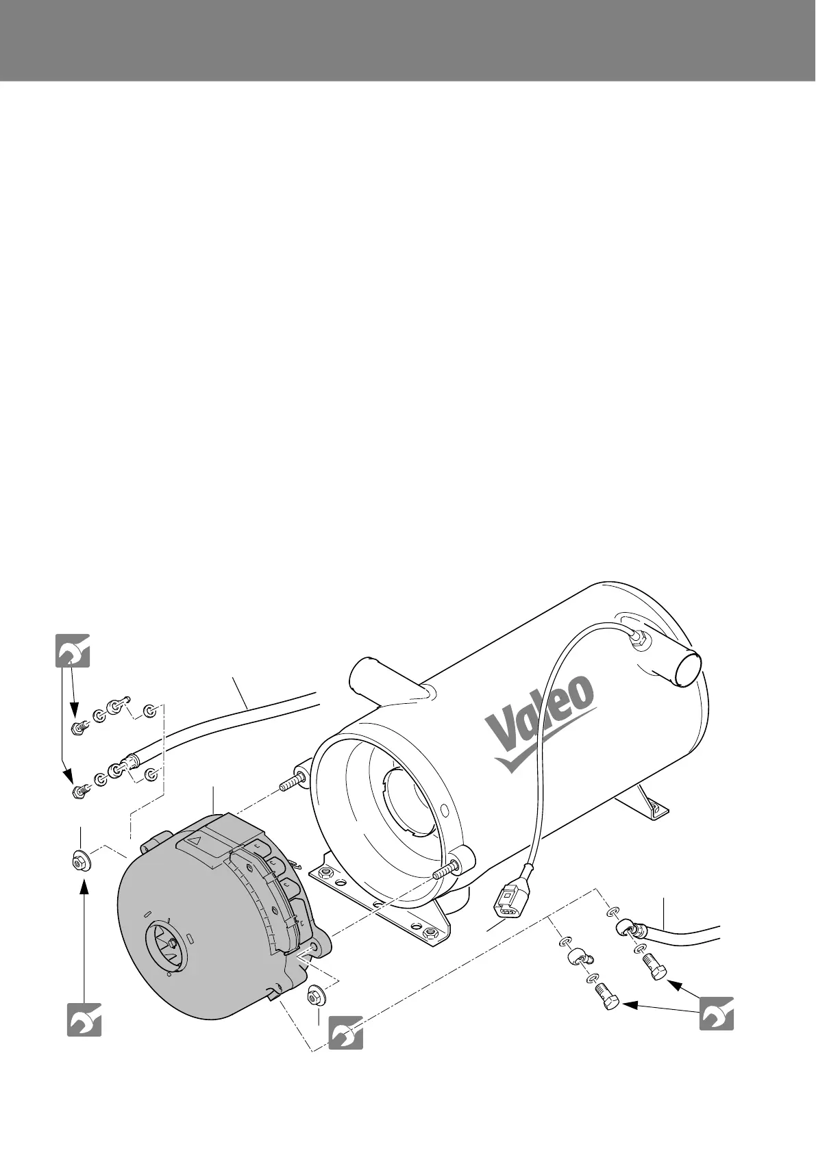
Fig. 801 Burner head removal and installation
1 Burner head (1)
2 Nuts (2)
3 Temperature sensor plug
4 Fuel line (2)
1
3
2
2
7.5 +1 Nm
7.5 +1 Nm
16 ± 1 Nm
16 ± 1 Nm
4
4