513
Thermo plus 160/230/300/350 5 Troubleshooting
5.6.7 Electronic ignition unit inspection
NOTE:
It is possible to manually test the functionality of the
electronic ignition unit, and using the Component Test
menu of the STT diagnosis.
It can only be verified by visual inspection of the ignition
electrode, whether the ignition spark jumps over to the
ignition electrode.
High voltage: The voltage received by the ignition
electrode is >13,000 Volt.
During operation or testing of the electronic ignition
unit, the ignition electrode may not be contacted by
persons or items.
ATTENTION:
Do not test or apply voltage to the electronic ignition
unit without an ignition electrode.
Inspect the electronic ignition unit for housing and end
cover damage.
No mechanical damage may be caused or be present on
housing and end cover.
Inspection using the STT diagnosis
• Remove the burner head (see 8.2).
• Connect the test plug instead of the temperature
sensor plug to the control device.
• Reconnect the heater with the vehicle electrical
system.
• Connect the STT diagnosis to the heater.
• Start STT diagnosis, establish connection to the
heater and open the Component Test menu.
• Select the electronic ignition unit in the Component
Test menu.
Enter a runtime. Next start the component test.
• Nominal condition: Ignition sparks at the ignition
electrode jump over with a rate of 6Hz.
• After the test is completed, exit STT diagnosis as
needed.
• Disconnect the heater from the vehicle electrical
system (Observe 5.2 !).
• Remove test plug.
• Install burner head (see 8.2).
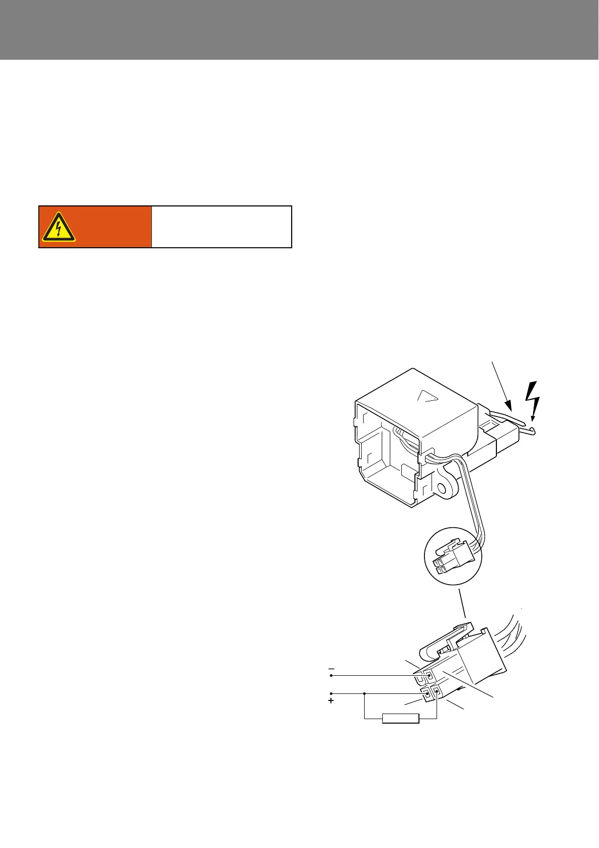
Manual functional test when disassembled:
• Remove electronic ignition unit (see 8.6).
• Connect ignition electrode.
• Apply 24V direct voltage according to Fig. 507
(10kOhm on SE input).
• Nominal condition: Ignition sparks at the ignition
electrode jump over with a rate of 6Hz.
• After the test is completed, install the electronic igni-
tion unit (see 8.6).
Risc of electric shock!
Warning!
Fig. 507
10k
Ignition electrodes 13,000 Volt
Pin 2
Pin 1
Pin 3
Pin 4