809
Thermo plus 160/230/300/350 8 Repairs
8.11 Fuel nozzle removal and installation
Removal
1. Remove burner head (see 8.2).
2. Lift off ignition electrode (2, Fig. 804) from the electro-
nic ignition unit by twisting a screwdriver sideways
and remove it.
3. Remove disc (5, Fig. 805).
NOTE:
Do not touch or attempt to clean the nozzle orifice.
4. Unscrew fuel nozzle (4). It is necessary to counteract
with a tool at the hexagon of the nozzle block of the
fuel pump (9).
Installation
1. Screw in the fuel nozzle (4, Fig. 805) and tighten. It is
necessary to counteract with a tool at the hexagon of
the nozzle block of the fuel pump (9).
2. Fit the disc (5) onto the nozzle holder of the fuel pump
(9) and align it so, the ignition electrode (3) may inser-
ted into the electronic ignition unit.
3. Insert ignition electrode (3) into the electronic ignition
unit.
4. Install burner head (see 8.2).
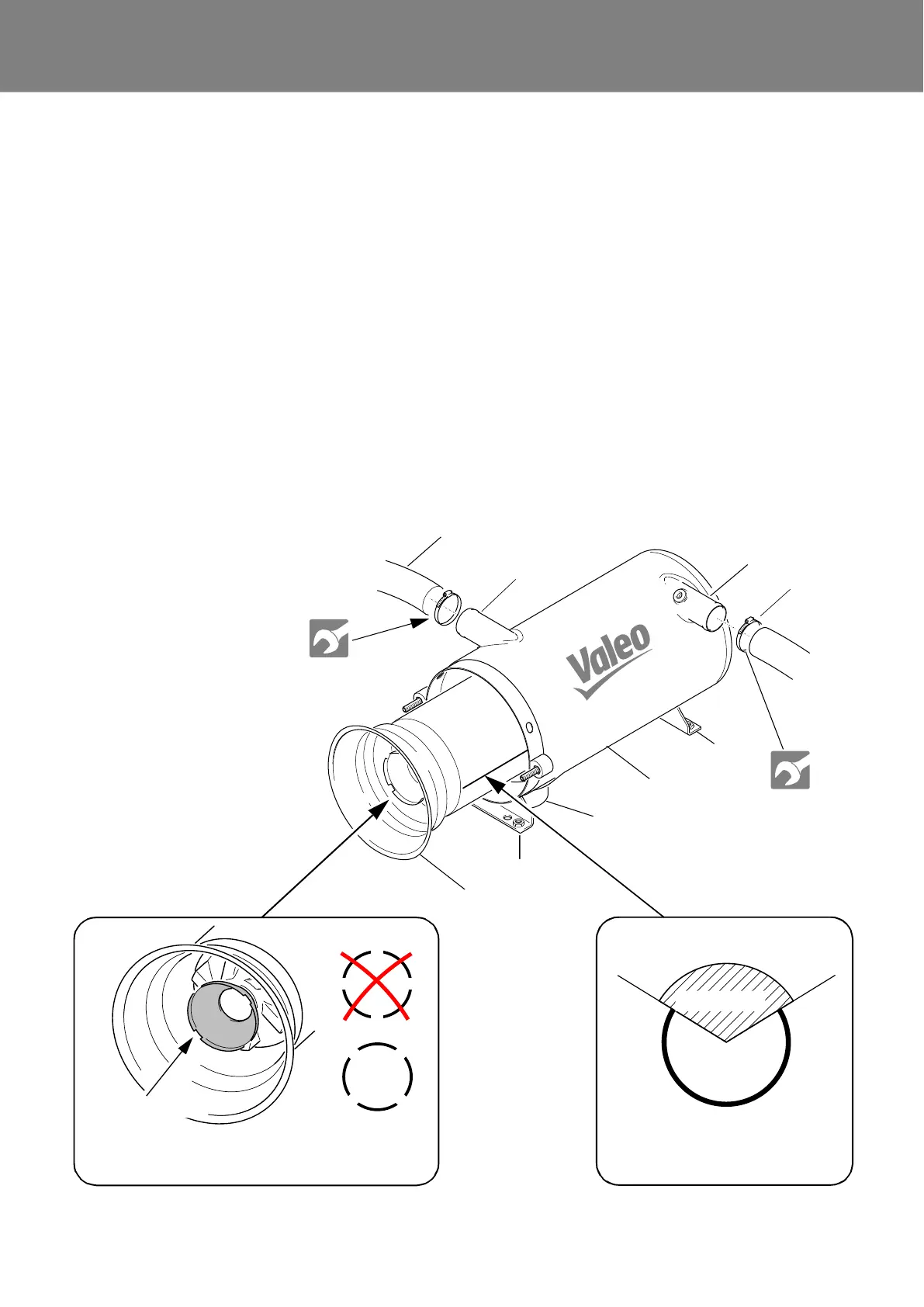
8.12 Combustion chamber removal and
installation
Removal
1. Remove burner head (see 8.2).
2. Pull the combustion chamber (1, Fig. 808) out of the
heat exchanger (2).
Fig. 808 Combustion chamber removal and installation
1 Combustion chamber
2 Heat exchanger
3 Exhaust outlet
4 Stand
5 Coolant inlet
6 Coolant outlet
7 Coolant hose (2x)
8 Hose clamp (2x)
Position of the welding seam
Position of the cut-outs in the combustion
chamber head when installed
when installed
1
4
4
6
3
5
2
7
8
6 ±0.6 Nm
6 ±0.6 Nm
Cut-outs
o.k.
Not permitted!