511
Thermo plus 160/230/300/350 5 Troubleshooting
5.6.4 Check of the temperature sensor with
integrated overheating protection
Prior to removing the temperature sensors, the over-
pressure in the cooling system must be released by
opening the cooling lid. Observe the risk of injuries
due to increased coolant temperature. Possibly let
the heater additionally cool down and have a collec-
ting container ready for discharged coolant.
Check
• Inspect temperature sensor, plug and cable for
damage and proper fit.
• Remove temperature sensor (see 8.3).
• Perform the electrical test using a measuring device
suitable for resistance measurements.
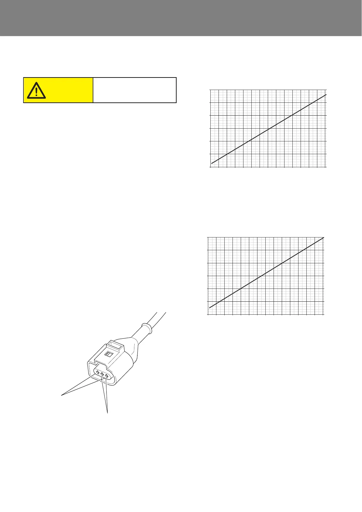
The water temperature sensor and the overheating
protection should indicate values according to the
charts. (Fig. 503 and Fig. 504).
Preferably the resistance should be measured at an
approx. consistent temperature of 20° C and approx.
100° C (immerse sensor up to the copper gasket ring
into boiling water).
Prior to reading the value, the sensor should be expo-
sed to the temperature for approx. 20 seconds.
A measurement tolerance of +/- 5°C under workshop
conditions is permitted.
• Reinstall temperature sensor (see 8.3).
Resistance vs. temperature charts
Fig. 502 Temperature sensor connector
Risk of scalds!
Caution!
Pin 1 & 3
Pin 2 & 3
Overheating protection
Water
temperature sensor
(PT2000)
(PT500)
Fig. 503
Fig. 504
Diagramm Widerstand über Temperatur
-40 -30 -20 -10 0 10 20 30 40 50 60 70 80 90 100
2850
2650
2450
2250
2050
1850
1650
Water temperature sensor (pin 1 and 3)
Resistance in Ohm
Temperature in °C
-40 -30 -20 -10 0 10 20 30 40 50 60 70 80 90 100
700
650
600
550
500
450
400
Overheating protection (pin 2 and 3)
Resistance in Ohm
Temperature in °C