Do you have a question about the Valeport 106 and is the answer not in the manual?
Overview of the Model 106 current meter's capabilities and operating modes.
Details on setting up and extracting data in self-recording mode.
Information on direct reading operation via PC or CDU.
Guidance on using DataLog x2 software for setup and data handling.
Describes the internal workings and measurement principles of the Model 106.
Provides physical dimensions and a diagram of the Model 106 instrument.
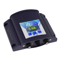
Discusses surface units like the 8008 CDU and PC connection options.
Instructions for physically installing the instrument, including impeller setup.
Details on connecting the instrument for different modes and using connectors.
Specifics for RS232 connections for PC operation and data transfer.
Connecting for self-recording mode setup and data extraction via SubConn.
Explains Digital Current Loop for longer cable lengths and CDU use.
Defines the data string format transmitted by the instrument.
Information about the instrument's internal and CDU battery types and life.
Details on batteries for the 8008 Control Display Unit.
Step-by-step guide for operating the instrument with the 8008 CDU.
How to configure sample and averaging intervals for the instrument.
Understanding display modes and managing CDU logging functions.
Starting the instrument and using profile mode for depth adjustment.
Important considerations and limitations regarding CDU data logging.
How to recover and read data stored in the instrument after deployment.
Details of the three external connections on the 8008 CDU.
Information on the printer output string format and compatibility.
Detailed format of the data string sent to a printer for the Model 106.
Explains the data storage format and maximum record capacity for the 106 and CDU.
Step-by-step guide for replacing the battery in the Model 106 instrument.
Instructions for replacing batteries in the 8008 Control Display Unit.
Procedures for removing, cleaning, and refitting the impeller.
Steps for cleaning the impeller and its components.
Guidance on correctly resetting the impeller shaft position.
Reassembly instructions for the impeller after maintenance.
General maintenance advice, cleaning, and contact information.
Lists the sizes of O-rings used in various parts of the instrument.
Procedure for replacing the memory back-up lithium battery.
Diagram illustrating various interconnection setups for the Model 106.
Diagram showing the layout of sensors and components within the Model 106.
Wiring details for the 10-way SubConn connector on the instrument.
Wiring specifications for the Y lead used for connections.
Wiring details for the comms and power lead between SubConn and Milspec.
Wiring for DC Input and RS232 connectors on surface units.
Wiring pinout for the deck lead used for fish input.
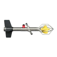
The Model 106 Current Meter is a versatile instrument designed for measuring water speed and direction, with optional capabilities for temperature and depth. It can operate in two primary modes: self-recording and direct reading, offering flexibility for various deployment scenarios.
At its core, the Model 106 is an impeller-based current meter. It operates on a basic 1-second cycle, during which it counts impeller rotations and takes a single compass heading reading. From these measurements, East and North velocity vectors are calculated and then summed over a user-defined averaging period. If optional temperature and pressure sensors are fitted, these parameters are sampled once every sample period and also averaged over the same period. It's important to note that for very low flow speeds (in the order of a few centimeters per second), a reasonably long averaging period is recommended to enhance the resolution and accuracy of the flow measurements.
The instrument incorporates a data acquisition micro-controller, operating at a 12-bit resolution. The temperature and depth sensors, if present, sample at a basic 16 Hz rate sequentially.
In self-recording mode, the Model 106 logs raw data internally. For real-time operation, the instrument's software uses built-in calibration constants to convert raw sensor data into actual temperature and pressure readings. When logged data is extracted, the raw data is transferred to a PC, where the accompanying Windows software automatically converts it into engineering units.
The Model 106 offers flexible power options. It can draw power from its internal battery, from the 8008 Control Display Unit (CDU) if used, or from an external surface battery or power supply. The internal battery, which can be either a 1.5V alkaline D cell or a 3.6V Lithium D cell, provides substantial operating life, ranging from approximately 30 to 90 days at a 10-second sampling rate, or even longer at a 5-minute sample rate. To assist users, the battery voltage is displayed in the DataLog x2 software, helping to determine remaining battery life.
The instrument is equipped with a 512K memory, capable of storing over 131,000 speed and direction records, or over 65,000 records if temperature and depth are also fitted, provided the data is stored in a single file. The 8008 CDU, if used, has its own 128K memory, allowing for storage of over 32,000 speed and direction records, or over 10,000 records with temperature and depth. Both the Model 106 and the CDU have a limit of 100 files.
The Model 106 can be configured and operated in several ways:
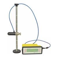
The instrument comes with a suspension assembly for attachment to a suspension or mooring line. Users must ensure that the maximum working load of the cable (100kgf for Valeport polyurethane covered multi-core cable) is not exceeded, especially if a sinker weight is used.
Before deployment, two critical procedures must be followed for correct impeller operation:
The Model 106 is supplied with DataLog x2 software for setup, data offload, and display, offering alphanumeric and graphical options. A separate manual details its operation. When using the setup wizard in DataLog x2, if no changes are made, the 'Finish' button may be greyed out. To resolve this, simply type a '#' into the command window to make the 'Finish' button available. After configuration, the instrument will be in a paused state and requires a command (#028 in Terminal window), a RUN button click in DataLog x2, or disconnecting/reconnecting the Power/Comms cable to activate.
Regular maintenance is essential to ensure the longevity and accuracy of the Model 106.
Battery Replacement (Model 106): The single D cell battery is located at the front end of the instrument.
Battery Replacement (8008 CDU): The 8008 CDU uses eight "C" cells (LR14 or equivalent), housed under the battery cover.
Impeller Maintenance:
General Maintenance:
O-Ring Sizes: Specific O-ring sizes are provided for various components (Line connector, Bulkhead connector pro-cap, Bulkhead Connector/Housing, End Cap, sensor end, Centre section/housings). Anti-extrusion backing rings are used on the sensor end O-rings and should be placed on the pressure (seawater) side. The temperature sensor uses a Dowty seal type 303.
Lithium Back-Up Battery: The memory back-up lithium battery (Type T047BA9, 3.6V) should be replaced every 5 years, or if memory/clock settings are lost. While it's recommended to return the instrument to Valeport for replacement, urgent renewal can be done as follows:
Calibration: Instruments are factory-calibrated using industry-standard methods, with a calibration certificate supplied. Impellers are group-calibrated at HR Wallingford, allowing them to be changed without recalibration. The calibration uses a seventh-order polynomial. If users need to recalibrate, the calibration constants within the instrument can be changed, and Valeport should be contacted for guidance on this procedure.
| Accuracy | ±0.01% FS |
|---|---|
| Resolution | 0.001% FS |
| Power Supply | 9-30V DC |
| Housing Material | Titanium |
| Output | RS232, RS485, SDI-12 |