3. Installation
3.1. Mechanical Installation
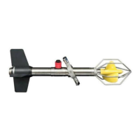
Impeller
Impeller
Guard
SubConn
Connector
Suspension
Assembly
Lock
Ring
Tail Fin
Assembly
The instrument is provided with a suspension assembly for users to attach to a suspension or mooring line. If
the Valeport polyurethane covered multi-core cable is being used, then this has a maximum working load of
100kgf, and if a sinker weight is being used, it is important that this load is not exceeded.
For correct operation of the impeller, two procedures must be performed prior to deployment:
1. The inner part of the impeller should be filled with clean water
This is achieved by unscrewing the impeller nose cap, and submerging the impeller to allow water to fill the
inside. While it is still underwater, refit the nose cap to seal the water inside.
2. The meter must be balanced so that it is suspended horizontally in the water
Due to the fact that the meter is made from materials of different densities, the balance of the meter will be
slightly affected by different salinities. For this reason, the suspension assembly can be moved along the
main body to compensate.
First, tilt the assembly to expose the lock ring around the main body.
Slightly loosen the 2.5mm socket countersunk 316 titanium screw, until the lock ring can be slipped
along the surface of the body.
Immerse the meter, and adjust the position of the suspension assembly until the unit sits horizontally
in the water.
Finally, tighten the 2.5mm screw to fix the lock ring in place. Do not over tighten.
Failure to observe these points will result in decreases in operating efficiency, accuracy and impeller life