Do you have a question about the Valeport TideMaster and is the answer not in the manual?
Describes the TideMaster tide gauge and its applications.
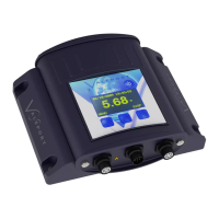
Details the TideMaster's OLED display, Bluetooth, and memory capabilities.
Provides a visual guide for mounting the device.
Lists technical specs for pressure and radar sensors.
Lists all components included with the TideMaster system.
Covers initial setup procedures for the unit and sensors.
Instructions for mounting the main logging unit.
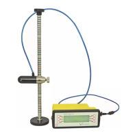
Guidance on installing the pressure sensor.
Steps to safely shorten the transducer's signal cable.
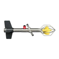
Installation details for the radar sensor.
Describes how to mount the radar sensor onto a boom.
Explains the process for directly mounting the radar sensor.
Procedures for ensuring the radar sensor is level.
Details on connecting the radar sensor's wiring.
Wiring instructions for the radar sensor junction box.
Procedures for calibrating the sensors.
How to calibrate the pressure sensor.
Calibration for the radar sensor.
Setting the operational working range of the radar.
Important safety warnings regarding battery usage.
Step-by-step guide to powering on the device.
Instructions for safely powering down the unit.
Procedure for replacing the unit's batteries.
Analysis of battery life based on different usage scenarios.
Battery life estimates for Scenario A.
Battery life estimates for Scenario B.
Battery life estimates for Scenario C.
Battery life estimates for Scenario D.
How to interrupt the TideMaster's current operation.
Configuring the TideMaster via its on-board panel.
Configuring sensor parameters and output units.
Configuring the TideMaster using PC software.
Establishing communication between PC and TideMaster.
Configuring the data sampling modes and parameters.
Detailed procedure for calibrating the pressure sensor.
Explains the formula for converting pressure to depth.
Setting up custom calibration parameters.
Calculation and input of the Gain Factor.
Setting the Datum Offset for calibration.
Performing calibration at the specific deployment site.
Site calibration using a stationary transducer.
Site calibration using a movable transducer.
Calibration procedures for the radar level sensor.
Defining the valid measurement range for the radar.
Calibration steps using the unit's display and buttons.
Calibrating the pressure sensor via the control panel.
Calibrating the radar sensor via the control panel.
How real-time data is transmitted and logged.
Configuring logging intervals for data files.
Setting the directory for daily data storage.
Specifying a location for data backups.
Defining a shared location for remote data access.
Loading and using tidal prediction files.
Instructions for retrieving logged data from the instrument.
Overview of available data visualization types.
Shows the latest numerical reading for a selected parameter.
Displays historical data in a tabular format.
Visualizes time-series data graphically.
Compares observed and predicted tide data graphically.
Shows the most recent readings from multiple sensors.
Graphical representation of wind speed and direction.
Information on loading and using prediction data.
How to save and load custom display configurations.
Command to halt the instrument's current operation.
Commands to initiate specific measurement modes.
Commands for managing logged data and settings.
Details on the structure and content of data files.
Format for data logged with pressure, tide, and met sensors.
Format for data logged with pressure, tide, and CT sensors.
Format for data logged with radar, tide, and met sensors.
Format for data logged with radar, tide, and CT sensors.
Formats used for transmitting data in real time.
Description of the NMEA output format.
Wiring diagram for the pressure sensor connection.
Wiring diagram for the radar sensor connection.
Wiring details for the WindSONIC sensor.
Wiring details for the METPAK II sensor.
Wiring details for the MaxiMet sensor.
Wiring details for the miniCT sensor.
Wiring information for the RS232 Y lead.
Details regarding UKCA conformity.
Details regarding EU CE conformity.
| Type | Tide Gauge |
|---|---|
| Power Supply | Internal battery or external power |
| Operating Temperature | -10°C to +50°C |
| Storage Temperature | -20°C to +60°C |
| Ingress Protection | IP68 |
| Resolution | 0.001% FS |
| Communication | RS232, RS485, SDI-12 |
| Material | Titanium |