2.2.3 Shortening the Transducer Cable
If a user wishes to shorten the signal cable, then this can be done, but care has to be taken in re-terminating
the connector in order to ensure the integral vent tube is properly terminated in the connector. If the cable is
shortened, the pressure calibration will alter slightly, but provided the site calibration is carried out, any
variations caused by the shortening of the cable will be taken account of. See Section 7.3 for Site calibration
method.
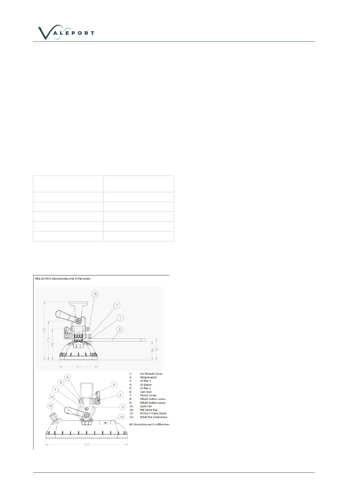
2.3 VRS20 Radar Level Sensor
The basic mounting requirements for the VRS-20 are a sturdy, stable surface or boom that does not
experience any significant vertical movement. The surface does not necessarily need to be level as the
VRS-20 mounting bracket features two axis adjustment.
The VRS-20 must have a clear view of the water surface throughout the expected working range with no
obstructions or fixed reflectors. The horizontal footprint of the radar is defined by the beam angle which is ±6
degrees. This approximates to a footprint radius of ~1/10th of the range.
The vertical datum of the VRS-20 is the front face of the instrument and all ranges are measured from this
point. With the input of a datum offset, the range values measured by the VRS-20 can be transformed to a
height value.