7
4. PRELIMINARY CHECKS
4.1 CHECK IGNITION SPARK
Before attempting to install, it is worth checking that the
piezo electric spark ignition system operates satisfactorily.
To initiate the spark, depress the control knob and while
keeping it depressed, turn anticlockwise through
approximately 60° to the “PILOT/IGN” position. A spark
should track from the electrode pin to the thermocouple
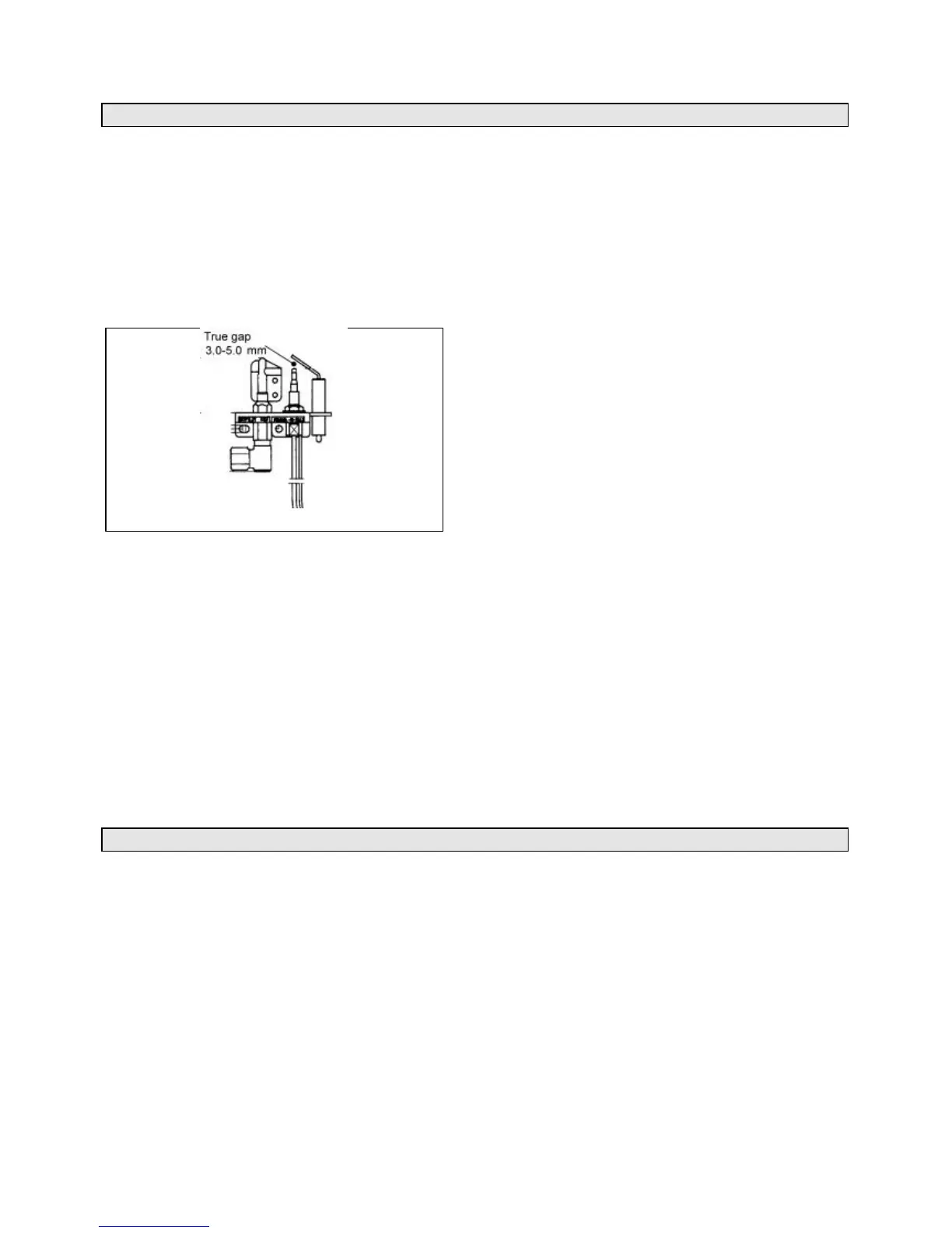
tip. If there is no spark or incorrect tracking, check the
spark gap between the electrode wire and thermocouple tip
(see figure 3). If the spark gap is correct, check the ignition
wiring.
4.2 CHECK THE FIREPLACE
The fireplace must comply with all the requirements of
section 2.
4.2.1 Fireplace general condition
The fireplace floor should be reasonably flat to ensure that
the convection box can be installed without it rocking and so
that a good seal can be made at the bottom front of the box.
The front face of the fireplace should be reasonably flat over
the area covered by the convection box top and side flange
seals to ensure good sealing. These faces should be made
good if necessary. If the appliance is to be fitted against a
wall with combustible cladding, the cladding must be
removed from the area covered by the outer surround (see
figure 1c). We suggest that the actual surround is used as a
template to mark the area for combustible cladding removal.
4.2.2 Soundness for appliance attachment
Two primary methods of retaining the appliance are
provided: -
1) By fixing to the fireplace front.
2) Using concealed tension cables fixed to the rear of the
fireplace opening together with secondary fixing to the
fireplace floor.
The methods are detailed in section 7 of this manual.
Before selecting the retention method, consult with the
customer. Method 2 is provided for instances where drilling
holes in the front surface of the fireplace surround is
unacceptable to the customer or otherwise impractical. N.B.
It is unwise to attempt to drill into marble without the
proper tools and equipment.
If method 1 is chosen, make sure that the fireplace front
surround area is sound enough to take the rawlplugs and
woodscrews. If necessary, make sound with a suitable
cement.
If method 2 is chosen, make sure that the areas at the back
and towards the centre of the fireplace floor are sound
enough to take the eyebolts and screws. If these areas have
deteriorated due to prolonged use, they should be made
sound with a suitable cement.
4.2.3 Installations using a metal flue box
The whole of the top surface of the metal flue box must be
covered with a layer of mineral wool or equivalent insulation
at least 100mm thick (see figure 1b).
4.3 FIREPLACE FLUE PULL
After preparing the fireplace, carry out the flue flow test as
detailed in BS5440: Part 1.
Note - A 13 gramme smoke pellet will generate the required
volume of smoke, anything smaller may give a false pass result.
Observe the smoke. If there is a definite flow into the
opening continue with the installation. If there is not a
definite flow, preheat the chimney for ten minutes and
recheck. If there is still no definite flow, the chimney may
need attention. Do not fit the appliance. Seek expert advice.
5. GAS SUPPLY CONNECTION
A nut and olive are provided for an 8mm pipe inlet
connection to the elbow at the bottom front of the
appliance. The elbow can be rotated to allow a connection
from any direction. The elbow includes a valve for isolating
the gas supply.
The supply pipe must be rigid material. Flexible pipe must
not be used.
5.1 CONCEALED SUPPLY PIPE
CONNECTION
If a concealed connection from inside the fireplace is
required then, before the appliance is fitted into the
fireplace it will be necessary to extend the supply line so
that it will project through the sealed opening at the back of
the convection box (near the left side) and run to the elbow
at the front
The pipe run from the supply line up to the rear opening in
the convection box must be kept clear of the area which will
be taken by the convection box when it is installed. A
template is supplied to aid the installation of the pipe run.
We recommend the following method for installing with a
concealed supply pipe:
5.1.1 Cut the template to the shape shown by the “Debris
catchment area”. Note that the areas are different for
fireplaces with conventional brick flues and precast flues.
5.1.2 Place the template on the fireplace floor (printed
side upward) with the front line level with the front surface
of the fireplace. The centre line of the template should line
up with the centre of the fireplace. Tape the template
securely in this position
5.1.3 Make sure that the fireplace is clear of all material
over the full area covered by the template including that
marked “Debris catchment area”.
Fig. 3 Pilot