6
Section 3: WiFi Module Kit (GV60WIFI)
Hardware
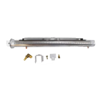
The GV60WIFI kit consists of:
• WiFi module
• Receiver connector cable
See "Hardware Requirements" on page 2 for full
details.
Installing the WiFi Module
See "Wiring Diagram" on page 3 for details.
1. Disconnect power to the appliance.
2. Connect cable from the WiFi module's RECEIVER
port to the SI port on the receiver.
3. Attach Velcro and place the WiFi module inside the
front panel of the fi replace per the diagrams to the
right in Module Installation Location. The module
should be placed with the RESET button facing up-
ward toward the opening.
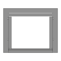
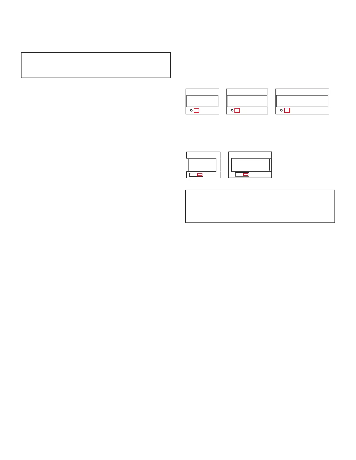
Module Installation Location
For Linear fi replaces (L1, L2, and L3), place the WiFi
module just to the right of the control valve, as
indicated below.
For LX fi replaces (LX1 and LX2), place the WiFi module
on the inside of the access plate just to the right of the
control valve, as indicated below.
Your installation is now complete. You may now sup-
ply power to the fi replace and proceed to "Valor 10 WiFi
Control Software Instructions", document 4007972.
L1 L2 L3
LX2LX1
Note
If installing in the LX2/2200 fi replace, be sure to
place the modules under the heat shield.
Note
This Section applies to all Linear and LX fi replaces.
 Loading...