985
Model Code Page
64. Powered front axle
1. 8. 1998
6000--8750 644 5
8. 11. 1990
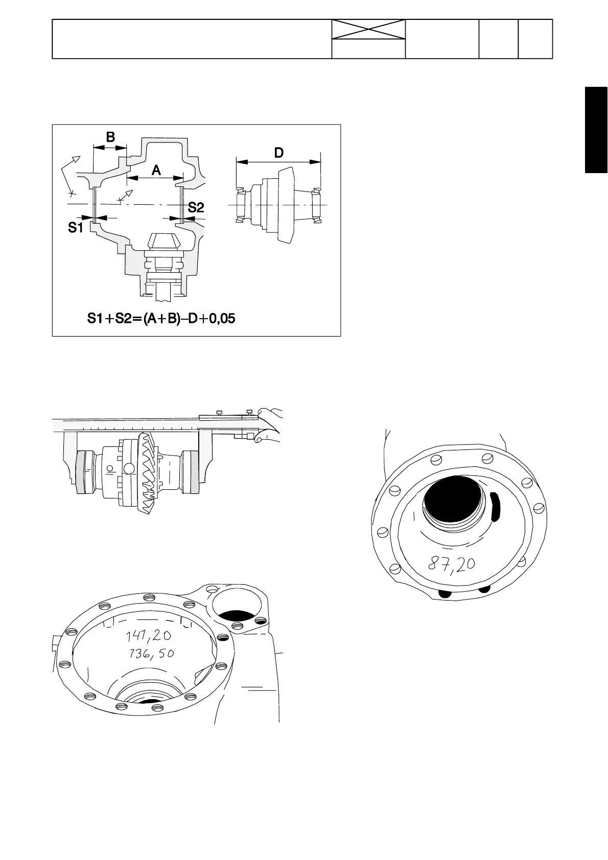
D. Adjusting differential bearing preload
and pinion/crown wheel tooth bac klash
Figure 7. Adjusting differential bearing preload.
1. Remove differential bearing outer races from both axle sec-
tions and remove any shims that may be fitted behind the
races. Remove roller bearings from the differential carrier.
2. Fit new bearings onto the differential carrier. Press outer
races against the bearings and use a vernier caliper to
measure the distance between them as shown in the figure
above, measurement D (e.g. 226,50 mm). N.B. When
measuring the use of measuring pieces is necessary.
3. Read off measurement A (larger figure) marked inside the
longer axle housing. This is the distance between the bottom
of the differential bearing location and the axle housing flange
surface (e.g. 141,20 mm).
Note! If no measurement can be found in the axle housing,
see page 644/6A.
4. Read off measurement B marked inside the shorter axle
housing. This is the distance between the bottom of the bear-
ing housing and the axle housing flange surface (e.g. 87,20
mm).
Note! If no measurement can be found in the axle housing,
see page 644/6A.
5. The preload (P) of the differential bearings should be 0, 05
mm. Calculate the number of shims required as foll ows:
S = ( A + B ) --- D + P =(141,20+87,20)---226,50+0,05
S=1,95 mm.
(141,20)
(87,20)
S=0,2
0,5